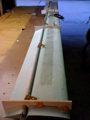
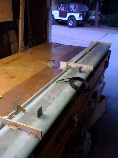
I apologize for not updating the website as I should but progress has been slow since I've gone back to school. Lynn and I have still been making some progress, we've hotwired the elevator foam cores and they are glassed and attached to the aluminum torque tubes with all bearing inserts pressed and riveted in. The NC-3 bearing "L" brackets are floxed into the canard and so completes the first moving surface on the airplane that amazingly moves without any binding or strange cracking noises. Here are some pictures:
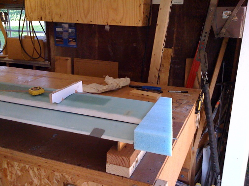
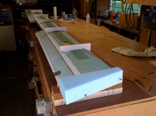
The plywood fixtures ensure the correct spacing between the elevator and canard since the elevator actually moves like a fowler flap. Because of the hinge point being at the bottom of the circular torque tube (apparent by the steel rod protruding from the end of the elevator bearing insert) the elevator actually translates down and aft allowing air to flow from the bottom side trailing edge of the canard over the top of the elevator. This increases the airflow over the top of the elevator giving it more lift or pitch up performance which is good for take-off. All of these pictures are with the canard/elevator upside down.


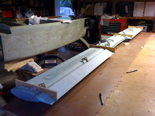
The copper colored "L" shaped brackets with the two holes are what the elevator pivots on. The portion of the bracket with the two holes will be embedded in the canard with flox. In these pictures they are resting on the top of the canard to determine where to cut the slots for installation.
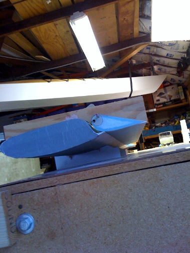
Here the wingtip foam cores are rough cut to size and microed to the end of the canard ready to be shaped. The white fixtures on the top of the canard are just so I can flip the hole assembly upside down to shape the bottom side. You can see the stainless steel hinge pin sticking out which is important, if this were to be pushed in beyond the the end of the foam it would not be possible to remove the elevators. The front has a nail pressed in to hold the foam core in place while the micro cures.
Friday Oct 9, 2009
Here are some pictures of the completed canard tip with the channel for the hinge pin. I glued some 36 grit sand paper to a restaurant type mustard bottle and shaped the foam per a template provided in the plans. I'll have to find the pictures of shaping the foam, that's what really intrigued me to this type of construction to be able to make complex shapes so easily.
The translucent perimeter of the tip is created by a fiberglass/flox/fiberglass edge or what's called a flox corner. A flox corner was made after the upper skin had cured then a 1/2 inch edge of the foam was sanded away and filled with flox and then the bottom skin layed up. This makes for a very tough edge. The trialing edge tapers nicely to just a glass to glass edge.
In case you missed this on the home page here's a Cozy video you must watch. Compliments of Aircraft Spruce & Specialty.
Well it took about a year and a half to finish my Master's degree and Project Management Professional (PMP) certification, couldn't have done it without Lynn's support, but we're back working on the airplane. That video sure is inspiring! The next step in completing the canard and elevators is adding counter balance weights to the elevator to prevent flutter in flight. The out-board balance weights need to be bonded to the leading edge of the elevator while the in-board weights are bolted to control arms that are part of the torque tube which resides within the fuselage. The out-board weights are bonded with 5 minute epoxy to foam which inturn is bonded to the elevator leading edge to hold them in place until two plies of UNI cloth eleven inches long can be wrapped around the entire assembly. Also the pitch trim control arm is pop riveted to the torque tube with 12 rivets, seems like 12 rivets is overkill.
Sunday July 18, 2010
Shown below are the counterbalance weights and foam wrapped with two plies of UNI overlaping onto the elevator. I also put a ply of BID on the sides to seal the foam.
These pictures show the recess cutout in the canard allowing for the balance weight travel. To obtain full elevator travel I removed all the foam until reaching the underside of the upper canard skin (the canard is sitting upside down on the table). It can also be seen that the elevator assembly balances nose down as specified in the plans for flutter prevention.
Here the required 0.1 inch gap can be seen as well as confirming the full aft stick elevator travel of 30 degrees.
The full down stick travel of -15 degrees is also confirmed.
Finally the recess is covered with one ply of BID employing flox corners with the bottom canard skin. Hopefully will still have full elevator travel. If the elevator travel checks out then that will complete the canard and elevator assembly and we'll be able to move on to Chapter-12 which is installing it on the fuselage.
The elevator travel checked out Ok so it's on to the canard installation Chapter-12.
Return Home Links Chapter 10 Canard Chapter 12 Canard Instal.