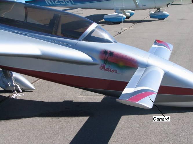
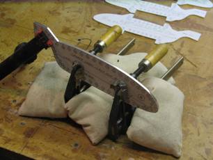
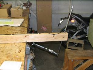
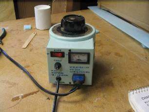
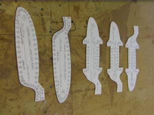
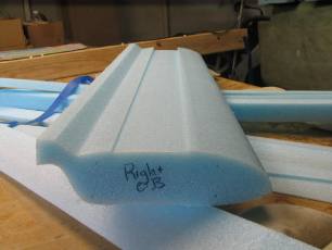
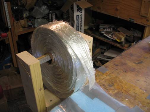
Finally started work on the canard, the small straight wing at the front of the airplane. Made a hot wire saw per the plans, using a piece of wood 2X4, 64 inches long and half inch solid steel rods. My brother-in-law Erik welded a hex nut onto one of the rods to make it easier to turn to tighten the .032 stainless steel safety wire. I also added a kill switch in case of an emergency. Made the templates from 1/16" aluminum since I couldn't find the formica that the plans called for. Match filed the templates so that they'd be identical. Bought a variac to control the voltage which worked very well in maintaining the wire temperature. The temperature of the wire is set based on cutting through the foam at rate of 1 inch in 4 seconds, it's a bit subjective but a good guideline. Another indicator of having the temperature set correctly is evidence of "angel hair" which is thin strands of foam that is produced when exiting the cut foam.
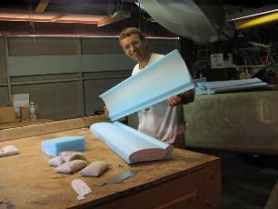
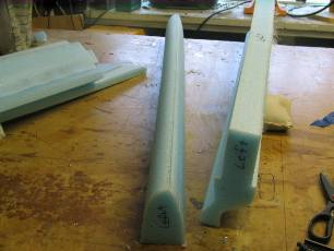
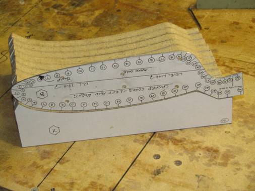
Lynn did all the hot wiring with me. It's imperative that you and your partner keep the wire straight while cutting especially while in a curved portion of the part. That is the reason for the numbers on the templates so that one person calls out the number that they're at and the other person tries to be at the same number. Initially we thought we were doing pretty well, all the air foil shapes came out very smooth and uniform looking. It's amazing how thin a piece of foam the hot wire can cut. Then when we had to cut off 8 inches from the inboard sections, to create the outboard sections (the canard is essentially made up of a middle section, 41 inches long, left and right inboard sections, each 43 inches long and left and right outboard sections which are each 8 inches long) we found out we weren't doing as well as we thought. After cutting off the outboard 8 inches we noticed that the new end of the inboard section was slightly smaller than the template by an 1/8 inch. After some emails to the Cozy group we decided to modify the hot wire saw so that it would be spring loaded to maintain tension on the wire while cutting the foam. It seems that the wire keeps stretching while it's hot, the spring will take up the extra slack. We also watched the "Building Rutan Composites" video and I think Lynn and I were much more careful and produced better foam cores than Burt and Mike Melville. But, with the spring loaded hot wire saw and tightening the wire just until we thought it would break, (the technique for tightening the wire is to pluck the wire and when the pitch stops getting higher then the wire is at the point of yielding) we were producing foam core sections that were within a 1/16" of the templates. Several of the more experienced builders said that was more than adequate since it will all be filled with micro during the finishing stage. The middle and inboard sections need to have a trough cut in them to allow for the fiberglass spar and a second set of templates are used to cut the trough. The trough is tapered so that the spar is thicker at the center and becomes thinner towards the outboard section of the canard. The spar needs to be stronger at the root to account for the bending loads created by the lift at the outboard ends of the canard.
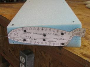
Then the nose of the airfoil section is cut off, because the cross section of the spar is in the shape of a "C". Once the spar is done the nose gets reattached. This is where I had another blunder, in that a nail was left in the cutting path of the hot wire and the hot wire went around the nail causing an unusable part, (the nails are used to keep the cut foam core in place in the original bed that it was cut from to keep it flat and stable for subsequent cuts). So I had to hot wire another right inboard airfoil section. The keyword here is "right" well I made another left inboard section, luckily I'd bought extra foam, knowing myself, and then cut another right inboard section. Despite me having an "Old Poop" attitude we hot wired some very nice airfoil core sections.
Sunday Sept 7, 2008
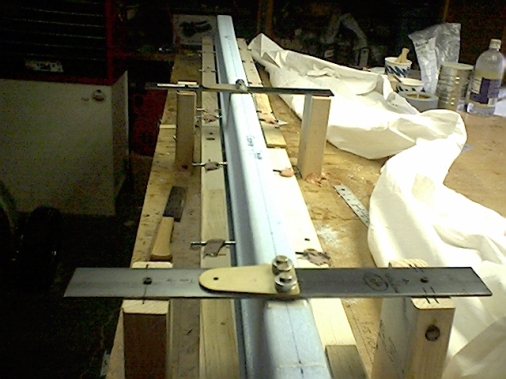
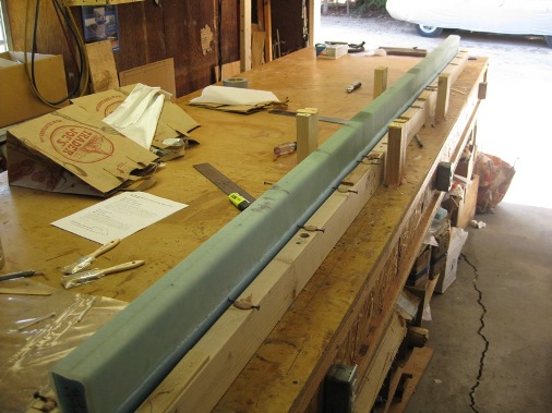
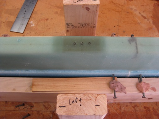
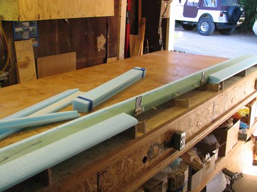
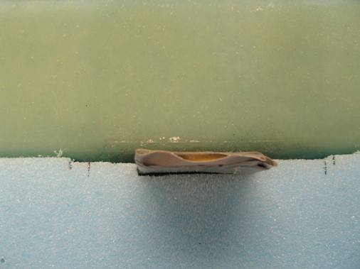
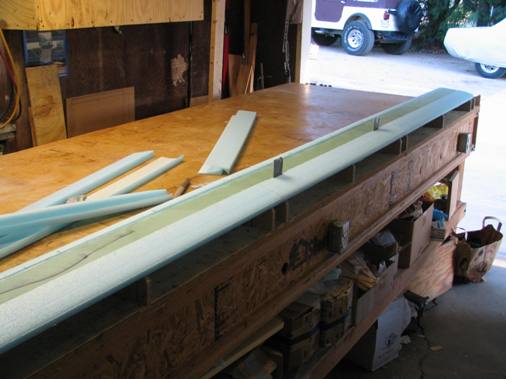
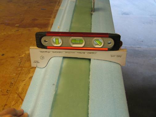
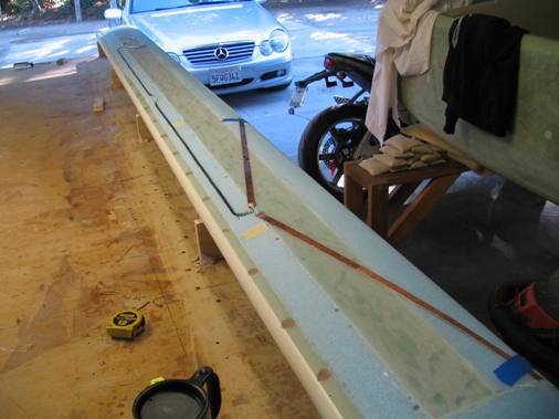
Unfortunately a problem occurred with my digital camera and I was unable to take pictures of joining the three foam cores. The cores are aligned between two parallel 2X4's 3.5" apart using nails to support the cores with the spar cap recess above the 2x4s. The goal, as usual, is to get the three cores straight and level. I strung a string along the trailing edge to ensure that they there were aligned straight and put shims under the nails as needed to make sure they were level with each other. I did manage to find my old Photo Phazer camera and took some pictures of bonding the lift tab nut plates in place. This is done with a piece of metal that will later serve as a drill guide because the nutplates will be covered with 17 plies of fiberglass and the holes will not be visible. Prior to fiberglassing over the nutplates the holes are filled with RTV to prevent them being filled with epoxy. I used black RTV so that they would be somewhat visible after the 17 plies of fiberglass are applied, and that did help a bit in verifying the location.
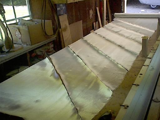
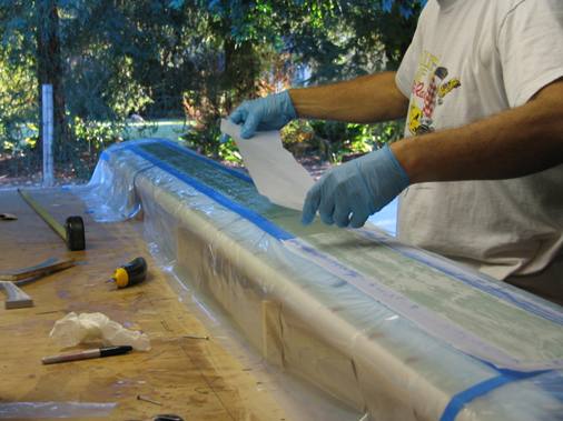
The uni-directional (UNI) fiberglass is cut at a 45 degree angle and 6 of the 7 plies are done with the UNI alternating the direction of the 45 degrees on each ply. Because the canard core is 125" long and you only get about 38" of length when cutting the UNI 10" wide at a 45 degree angle, you need three pieces of UNI for the first ply and each subsequent ply is a bit shorter than the next, so there are more plies built up in the center of the canard than at the tips. This is because the center must carry more of the bending loads. The 7th ply is a piece of bi-directional (BID, fibers running in two directions, 90 degrees from each other) cut at 45 degress that covers the middle section, then there are 9 plies of 1.5"x4" BID over the two nutplate tab areas and then a final piece of 8"x4" BID over that. So the lift tab mounting areas are built up with about a 1/4 inch of solid fiberglass. It took Lynn and I five and a half hours to do the entire layup.
The next step is to drill the bolt holes through to the nutplates using the steel drill guides, sorry didn't get any pictures of this, was too anxious to get it done. It was lucky I had set the drill guides up initially and marked the bolt holes because once I started drilling, the drill guide started to move slightly, I could realign the guide with the marks I made and then shimmed the vertical 2x4 uprights against the long 2x4 fixture. Because I have a layer of masonite on top of the table and the 2x4 vertical uprights are just bondoed to the masonite I think the masonite allowed the movement. I should have screwed the masonite down with some drywall screws in the areas of the uprights. I put a drill stop on the drill bit at about 3/8" from the tip which allowed me to drill down just to the black RTV plug. I screwed a small drywall screw into the RTV plug and could then pull them out cleanly.
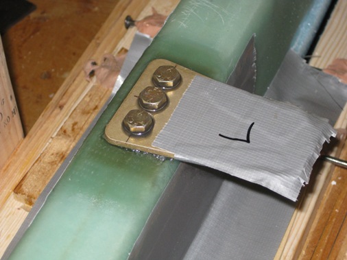
So the moment of truth was to see if the holes in the lift tabs would line up with the holes through the 17 plies of fiberglass through the 1/8" aluminum plate and into the nutplates. A couple of the holes needed a little massaging with the Dremel for the bolts to thread in straight but I was very happy that the tabs could be bolted down (torqued to 50 in-lbs) without any forcing, stripping or loud bangs. I sure hope I never have to remove those lift tabs, because they're on for good.
Sunday November 30, 2008
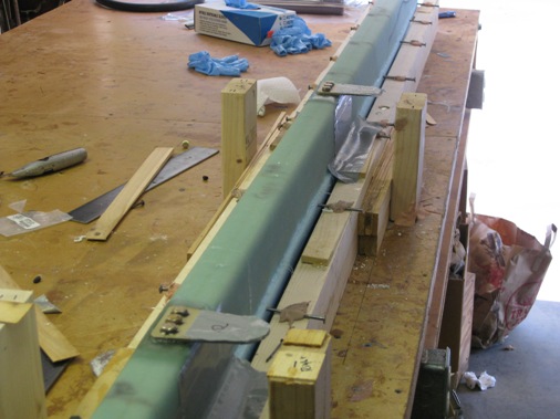
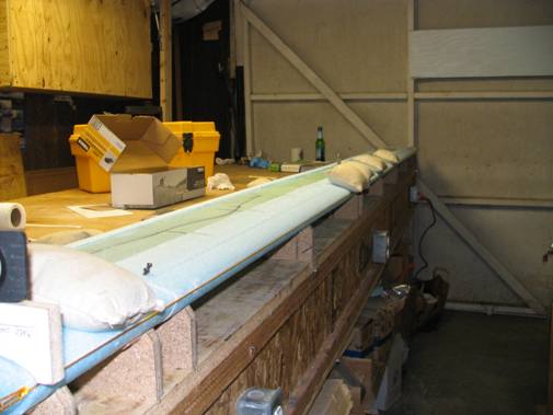
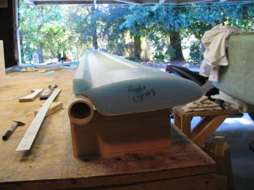
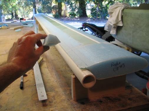
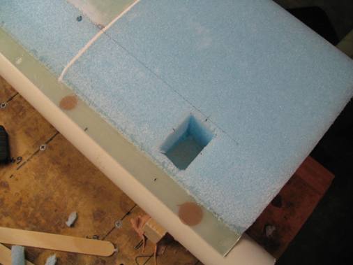
Wow, looks like I've got a lot of catching up to do to the website, done a lot since September. Now that the lift tabs are on it's time to reattach the nose leading edge. To start you need to cut out about 11 templates from 1 inch think particle board that are the shape of the top of the canard to hold it in place. These are bondoed to the table after making sure the table is flat and level in every direction. The flatness of the table is becoming more and more challenging with all the bondoing that gets done to it, I might have to replace the masonite top sheet soon. With the templates bondoed to the table the canard can lay upside down on the bed of templates and with the wood alignment dowels pushed in from the trailing edge the nose leading edge can be trial fitted. The center piece will take a little bit of work to make a recess to accommodate the lift tabs.
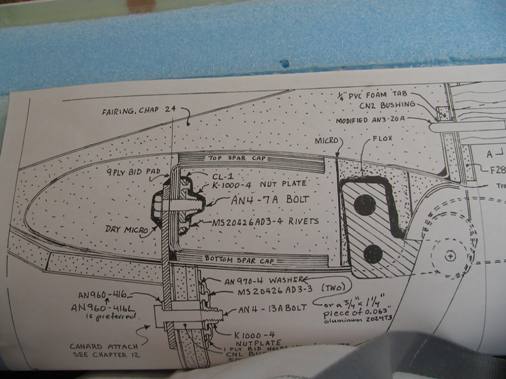
It also necessary to make sure the canard is level in the bed of templates and to ensure there is no twist, some shimming under the canard made sure of this. A plans cross sectional view may help (or not) make sense of what's being done. The bolt in the center is one of three that is holding the lift tab. The shear web is underneath the lift tab that is in the shap of a "C". Once the nose is attached the bottom spar cap will be layed into the trough.
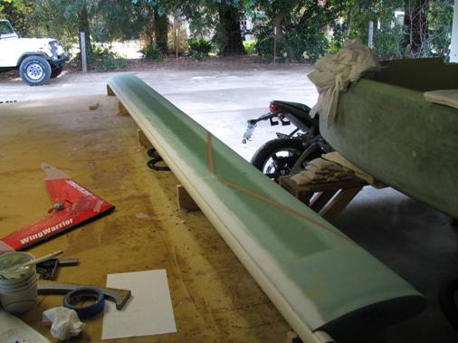
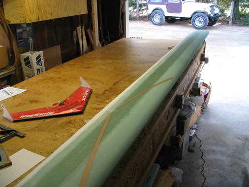
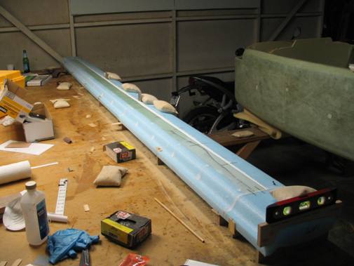
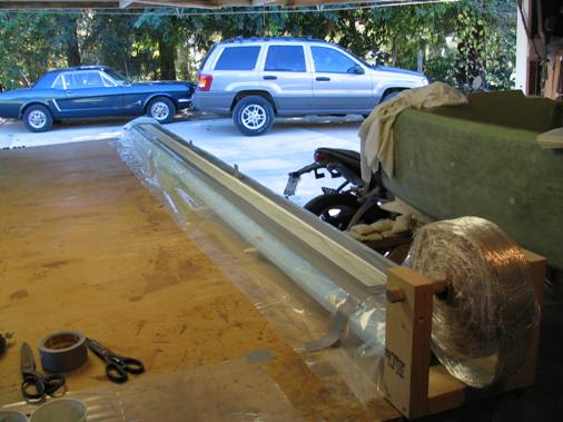
After a lot of fiddling, himming and hawing I bonded the nose leading edge and outboard ends back on, trying to make sure everything was straight and level.
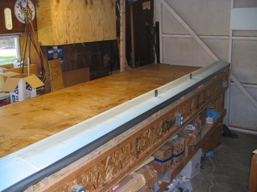
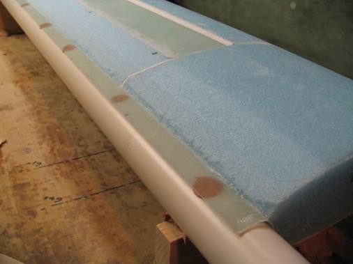
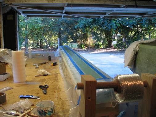
Now that nose and outboard blocks are on it's time to do the bottom spar cap layup. The spar cap fiberglass is different than the UNI and BID cloth used in all the previous layups. While it's called a spar cap tape it's actually about 24, 1/8 inch diameter rovings (3 inches wide) loosely held together with a cross thread that is pulled out once the tape is layed down. The number of layers of tape is dictated by the depth of the trough which is tapered, being deeper in the center and becoming shallower and the outboard tips. So the spar cap tapes become shorter as each layer is applied. A bottom template is used to check that the trough is fully filled. The foam is masked off to prevent epoxy drips messing it up.
It took 9 plies of the spar cap tape to fill the trough which is a ply or two more than typical, which after cure I found that I overfilled the trough by a ply or two which needed to be sanded off to maintain the airfoil shape of the canard. Talk about trying to sand a rock, this stuff is crazy hard.
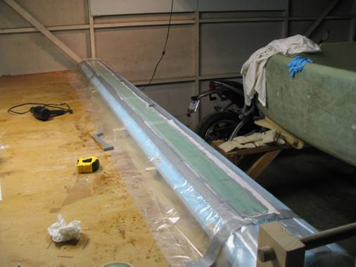
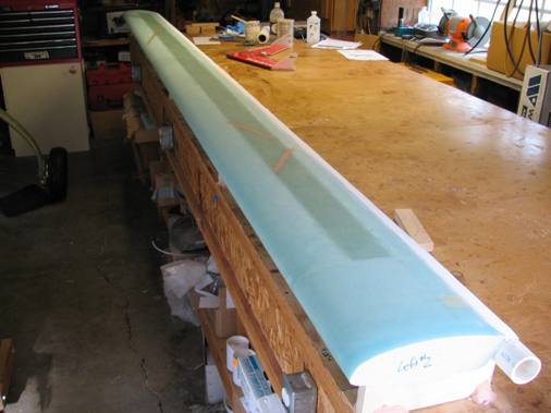
The bottom skin is 3 plies total, a ply of UNI, than a ply of BID and another ply of UNI. The UNI glass is layed up parallel with the length of the canard. There's a strip of peel ply about an inch wide layed up on the trailing edge to allow for a skin to skin bond with the top skin later, if that makes any sense.

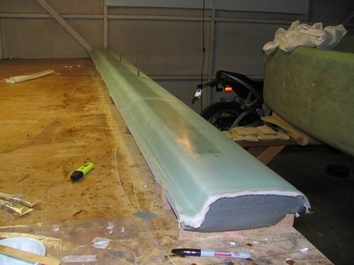
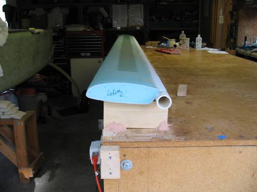
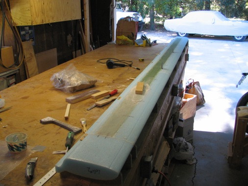
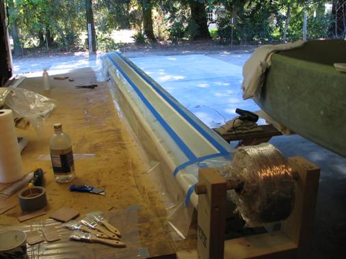
Now it's time to flip the canard over and do the top spar cap and skin. Another jig is built from a 1 1/4 inch pipe and 5 pieces of wood 1x4x8 to support the canard upright. Again everything is shimmed to keep the canard straight, level and untwisted. Since the bottom is already skinned it's possible to bondo the bottom directly to the wood and pvc pipe. In this step, what's called the fish tail, is cut off and then the 1" wide peel ply strip pulled up to enable a direct bonding between the top and bottom skins.
As is the case with everyone else, after the peel ply is pulled up there is a step between the foam and the bottom skin. I'll handle this the same way as what's called out in the plans for the elevator trailing edge and round over the step a bit so the top skin glass will lay in smoothly and fill above the top skin with mircro thereby maintaining the integrity of the top/bottom skin bond. Also started to hog out the holes for the high density foam inserts for the elevator hinges (see the plans cross section where a "L" bracket is floxed into the canard). The placement of these holes was a bit ambiguous in the plans, the dimensions are provided spanwise but only say aft of the spar so I measured a 1/4 inch aft of the spar on the cross sectional drawing which which is to scale and put them there.
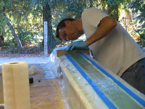
So, before the entire Thanksgiving weekend got away from me, Lynn and I did the top spar cap layup. Same as the bottom only more plies of spar tape since the trough is slighly deeper. I really wanted to keep from overfilling the trough this time since it was such a pain to sand the excess off. We did manage to lay in eleven plies of glass without overfilling, maybe slightly underfilled, but another ply would have put it over. Used blue masking tape this time instead of the duct tape to prevent bleed through of the epoxy on to the foam. In hind site this was a mistake, it seem to prevent the bleed through better but there is about of an 1/8 inch wide strip that is epoxied to the foam that I will have to remove with a razor blade.
Sunday January 4, 2009
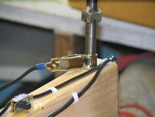
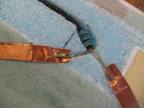
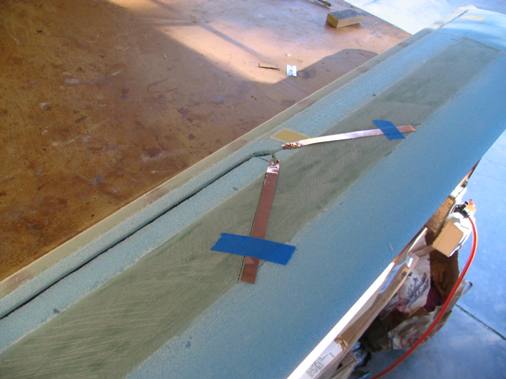
Happy New Year to everyone! Managed to get something done over the holiday break. Decided to imbed a navigation and a glide slope antenna into the canard while I had the chance. Routed the RG-58 coaxial cable about 1.5 inches forward of the trailing edge and exit through the bottom 3 inches forward of the trailing edge and 3 inches to the right of center (no particular reason other than to avoid interference with future construction). Per the RST antenna instructions the dipoles of the nav antenna are 22.8 inches and the glide slope is 7.5 inches. The lengths are based on the signal frequencies and can be easily calculated and the angle can be between 10 and 30 degrees (from horizontal). Three baluns are threaded onto the coax cable to strip off the reflective energy to prevent interference with other signals in the airplane. The dipoles are made of copper tape and the coax cable is simply soldered to them. This antenna stuff is black magic to me so I just try to follow the instructions.
Lynn and I spent most of New Years Eve glassing the top of the canard, from 10:30am to 6:30pm, still plenty of time to party though. Much of the time was spent micro'ing dings and dents in the foam and creating a small fillet for a smooth transition for the trailing edge glass to glass bond. We let this thick micro cure for about an hour so it wouldn't flow out when applying the thin micro to the rest of the foam. The top of the canard gets four plies of glass, 3 plies of UNI and 1 ply of BID. The layups went on very easy much like the bottom but with the experience of doing the bottom seemed pretty routine. There was an added complexity of having to stagger and overlap the top plies onto the bottom around the leading edge which got a bit messy fiberglassing upside down and took more time. Also because of the step at the trailing edge we added micro on top of the last ply to fair that a bit, still retaining the glass to glass bond, this is how the trailing edge of the elevators are treated.