 Friday July 23, 2010
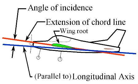
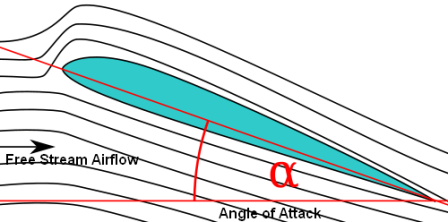
This is one of the shortest chapters, only 2 pages, but it's critical to mount the canard correctly in the fuselage especially making sure that the angle of incidence is correct along with the canard being level and perpendicular to the fuselage. The angle of incidence is the angle between the chord (an imaginary line drawn from the leading edge to the trailing edge of a wing in a profile view) of the canard and the longitudinal axis of the fuselage. The angle of incidence is important because the design of this airplane is based on the canard stalling (losing lift) before the main wing. The idea is that the main wing never stalls and is always flying producing lift. A wing generally produces more lift as the angle of attack (AOA) increases (of course drag also increases thereby requiring more power) up to a certain point where the angle is so great that the airflow separates from the wing and the wing stalls and loses lift, rather abruptly. The angle of attack (AOA) is the angle between chord of the wing or canard and the free stream airflow. Theoretically when the airplane is in straight and level flight the angle of incidence and the AOA are equal, then as you pitch the plane up the AOA becomes greater than the angle of incidence but the difference between the canard and the main wing AOA’s is still the same difference as their respective angles of incidence. Since the angle of incidence of the canard is set greater than that of the main wing the AOA of the canard will also always be greater then the main wing causing it to stall before the main wing has a chance to stall. When the canard stalls the nose of the airplane pitches down thereby reducing the canard AOA causing it to regain lift and the nose pitches back up. If the pilot were to hold the control stick full aft the nose of the airplane would bob up and down or porpoise continually with a gradual loss of altitude, this is because the larger main wing is carrying most of the load which hasn’t stalled. The advantage of a canard type airplane is that both the canard and main wing produce lift, while on a conventional airplane the horizontal stabilizer in the tail actually produces down or negative lift to balance out the weight of the airplane or center of gravity (cg) which is forward of the lift of the main wing. The center of gravity on a canard is in-between the canard and main wing but closer to the main wing. As it also is on a conventional airplane it's critical for a canard type plane to keep the cg within range specifically not letting it be too far aft which could overpower the controllability of the elevators and allow both the canard and main wing to stall causing the plane to drop, nearly vertically (with some forward velocity) in a nose up attitude. There have been reports of this happening with the pilot surviving the impact with the ground or ocean with minor injuries. Survivability can be attributed to the robust construction design, the relatively supine seating position and the proper type of cushions. So the point I’m trying to make is that getting the canard incidence set correctly is important and will take a lot of sanding, filing, filling and trial fitting to get it right.
Images compliments of Wikipedia.
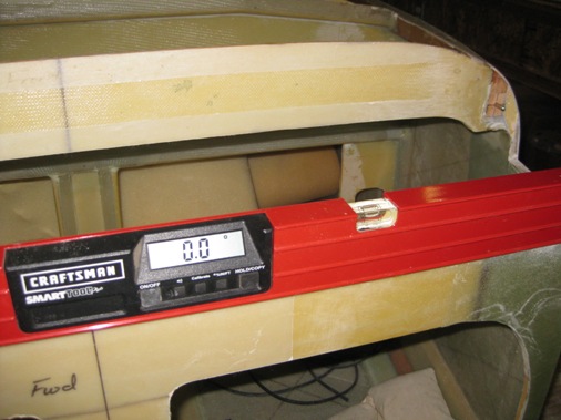
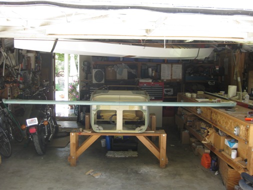
The first task is to make alignment pins by cutting the heads off some AN3 bolts and filing the ends round. Then drill two holes into the F22 bulkhead 1.5 inches deep for the pins to be installed. The alignment pins hold the canard at the correct angle of incidence. I first drilled a hole in a block of wood with a drill press to have a straight perpendicular hole to use as a guide for drilling into the bulkhead since the fuselage doesn't have many straight reference lines. To make sure the canard is installed correctly the fuselage needs to be leveled in every direction, I managed to level the fuselage laterally in three locations and longitudinally on both sides and on bulkhead F22 to an accuracy of 0.0 degrees, only took about an hour and a half to manage that.
Sunday July 25, 2010
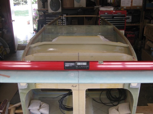
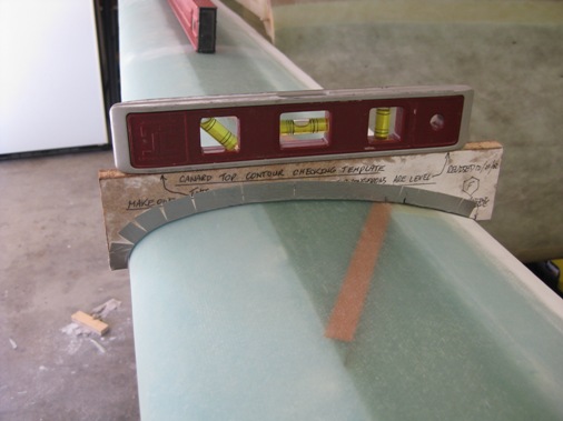
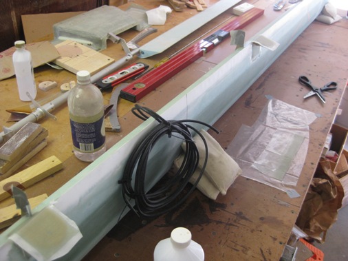
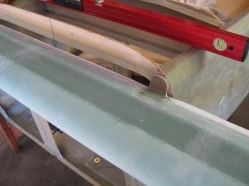
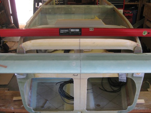
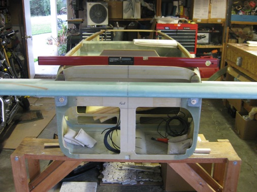
Now it's time to get the canard to sit on the fuselage; level, perpendicular and at the right angle of incidence. With some judicious sanding of bulkhead F22 I was able to get the canard to sit level. Perpendicularity is determined by measuring from the wingtips to the fuselage center line on the rear firewall and confirming that both measurements are equal, it's typical to have to shim one side to get equal measurements. The correct angle of incidence was accomplished by sanding the fuselage sides so that the trailing edge of the canard sat lower. With the canard sitting correctly on the fuselage it's now necessary to build up the fiberglass pads on F22 so that the canard lift tabs sit flush against F22. The shims are measured to determine how much fiberglass is added to the mounting pad. Fiberglass is also added to account for the angle of incidence causing the tabs to stick out at an angle relative to bulkhead F22. 1 ply of BID is equal to .013 inches and 1 ply of UNI is equal to .009 inches. Because of the angle of incidence causing the tabs to angle out some of the fiberglass plies had to be stair stepped to accommodate the angle. Needed about 10 plies on the right side and 17 on the left. After cure I sanded the pads flat and remeasured and sanded several times until the canard was perpendicular again.
Friday July 30, 2010
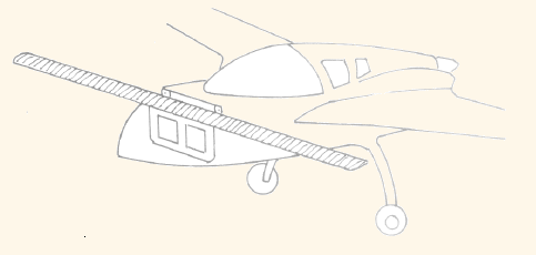
Now that everything was level and square you introduce another item to throw everything off. Because the tops of the bulkheads and fuselage sides will get a ply of BID on top you now need to compensate for that thickness with .016 inch thick aluminum shims. My hardware store didn't have aluminum that thin so I laid up a ply of BID 3/4 inch wide and after cure used them as my shims and they turned out to be about .016 inches thick. This of course caused the canard not to be level so some more final sanding to get it exactly right. Now with everything level and square I drilled the holes through bulkhead F22 using the lift tab pilot holes while Lynn watched to make sure I kept the drill level and perpendicular. I didn't take a picture so here's a sketch from the plans.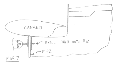
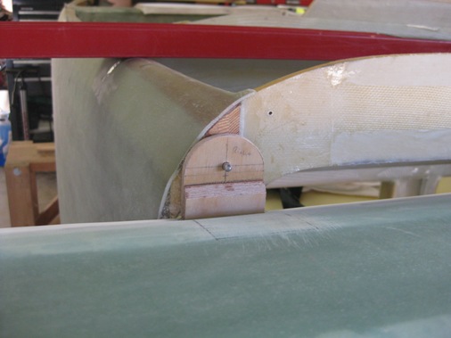
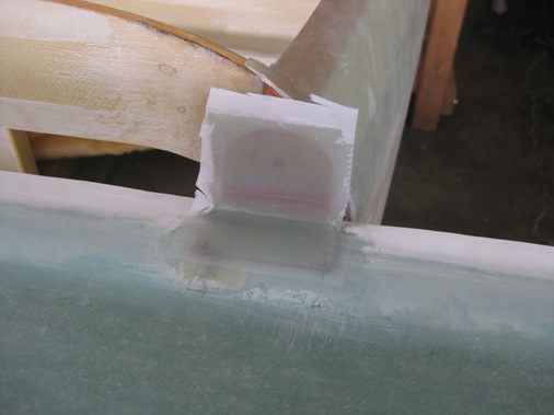
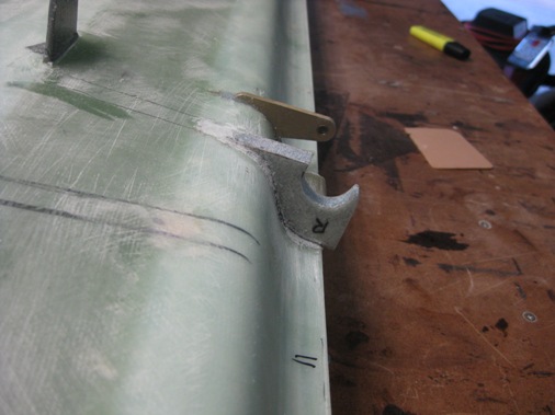
A couple of AN3 bolts are put through the lift tabs and F22 bulkhead holes to keep the canard aligned while you make the alignment tabs for the top of the canard. The lift of the canard also creates a moment coefficient or twisting, trying to lift the canard trailing edge, the alignment tabs react to this moment. The alignment tabs are made of birch plywood and because of the gap between the canard trailing edge and bulkhead F28 I needed a doubler on the bottom portion of the tab. The tabs are made so that they just touch the trailing edge of the canard and after doing this I noticed the 1/2 inch wide strip of micro along the trailing edge and became concerned about whether the subsequent 5 ply layup over the micro would be structurally sound, so I queried the Cozy Builders Group and was advised that for structural components not to layup glass over micro so I sanded the micro off in the localized area and made another set of longer tabs. A 1/16 inch thick washer is put behind the tabs to accommodate the 6 plies (is really 4 plies, see below) that are applied to the back of the tab later. With everything lined up and no binding of the alignment pins the tab is epoxied to the top trailing edge of the canard. Once cured 5 plies of glass is layed up over the tap and 1.5 inches on to the canard.
Sunday August 1, 2010
Once the glass on the front face of the tab had cured I trimmed the layup, rounded the bottom corner and we layed up 6 plies on the aft side of the tab. A good habit I picked up from Rick Maddy is highlighting that portion of the plans once that task is complete. While doing this I noticed that the plans called out, 4 plies of BID on the aft face of the tab, not 6, unfortunately I noticed this much too late and the layup had already cured. So I will have to sand off the equivalent of two plies of BID. Not a big deal, the challenge will be to keep the aft face of the tab flat. I'm not sure how I got in my mind that it should be six plies.
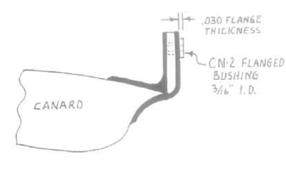
I sanded the back side of the alignment tabs to get a thickness equal to four plies of BID (4 X 0.013 = 0.052), just slightly thinner than the 1/16" (0.0625) thick washer that was used as a spacer. With some fresh 36 grit on my sanding block this took no time at all and I actually made it slightly too thin especially at the corner where the glass wraps around to the canard underside, so I applied a ply and a half back on. The half ply extends 1.5 inches on the canard to just below the hole in the alignment tab. With digital calipers it was easy to verify that the thickness was now correct. I should probably explain my concern for having too many plies on the back and that is because it would cause the canard leading edge to be pushed down slightly reducing the angle of incidence. The canard also didn't fit very well; there was some binding getting the bolts through the lift tabs and F22. Now the canard fits better and everything is still, straight, level and at the proper angle of incidence. I still have a concern because the bushings that are later inserted into the alignment tab holes (after they're enlarged) have a flange that adds another 0.030 thickness. The difference between the thickness of the washer (0.0625) and the 4 plies of BID (0.052) is 0.0105 which can be subtracted from the 0.030 flange thickness which gives an overall added thickness caused by the flange of 0.0195, call it 0.02 that needs to be accommodated for somehow or hopefully it won't make a difference.
Thursday August 26, 2010
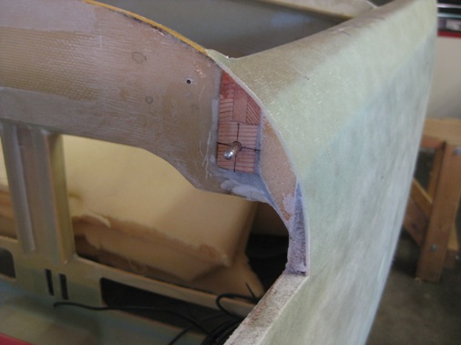
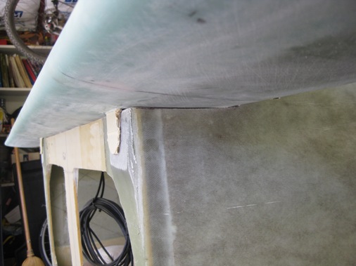
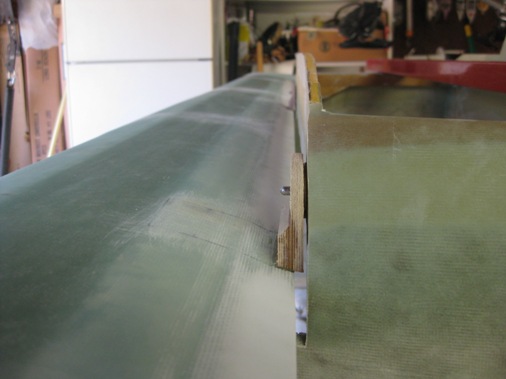
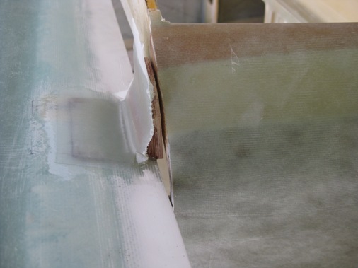
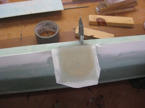
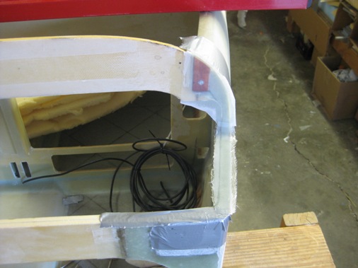
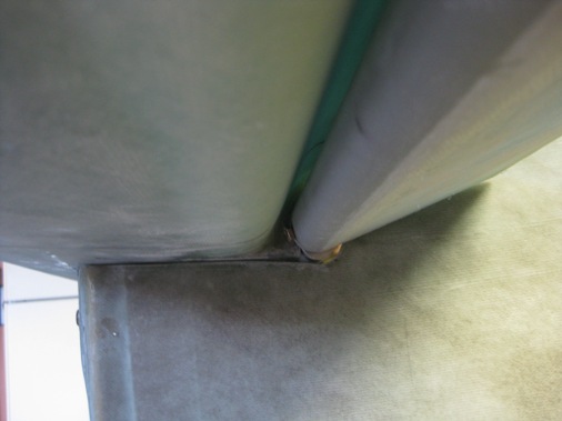
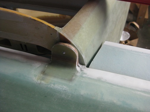
In the mean time I've drilled out the holes in the alignment tabs to 1/4 inch and floxed in the bushings and drilled out the holes in the lift tabs and through the F-22 bulkhead to 1/4 inch for AN4 sized bolts. The holes in F-22 will eventually be drilled out to 5/8ths to accommodate a bushing that will be installed later in Chapter 13. The photos below show the fabrication of a filler piece to help close up the gap between the bottom of the canard and the fuselage and floxing the top of the fuselage sidewall and up the F-28 bulkhead and covering with one ply of BID, (the alignment pins were not floxed in at this point).
The following pictures show the filler piece closing up the gap between the canard and fusealge and also the trimmed inboard end of the elevator providing clearance with the fuselage side and finally everything is still level square and at the correct incidence. So that wraps up Chapter-12 and on to 13 with the retractable nose gear.
Lift Tab Scratch Return Home Links Chapter 11 Elevator Chapter 13 Nose & Nose Gear