 May 18, 2021
May 18, 2021
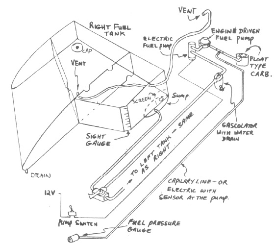
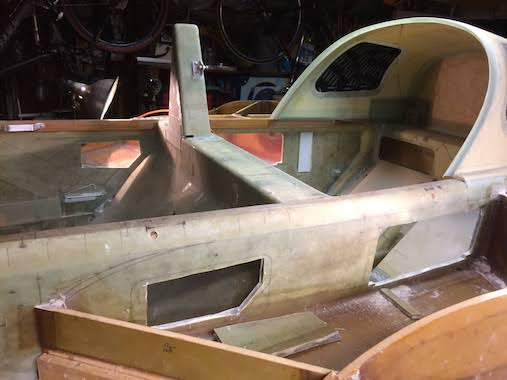
The strakes blend the wings into the fuselage and are aerodynamic, producing lift, so they need to be at the correct angle of incidence (angle relative to the fuselage). They also function as fuel tanks holding approximately 30 gallons in each side. Because the strakes hold fuel it's necessary to switch to a more fuel resistant epoxy a brand recommended by Gary Hunter (the group's epoxy guru) in this CSA Epoxy Article is EZ-Poxy with E87 hardener. Because the ratio of resin to hardener is different I can't use the epoxy pump for the MGS epoxy which I've been using for all the structure up to this point. From the email group I found that some builders use West System pumps. The pumps almost deliver the correct ratio for the EZ-Poxy/87, I only needed to add a hose clamp to the neck of the resin pump to limit the travel, slightly reducing the amount that it dispensed. I check the ratio with each use with a digital scale and so far it's been accurate every time. Since I plan on a fuel injected engine there will need to be a return fuel line to return the fuel to the same tank that is supplying fuel to the engine. So I am planning on using an Andair Duplex Fuel Valve, since it's a dual valve it will send the return fuel to the same tank (left or right) that is supplying fuel to the engine. This will of course add some plumbing (6 fuel lines and 4 vent lines) to the plan's schematic shown to the right. I also plan to add capacitance probes to measure fuel quantity in each tank and provide the information to the glass panel displays.
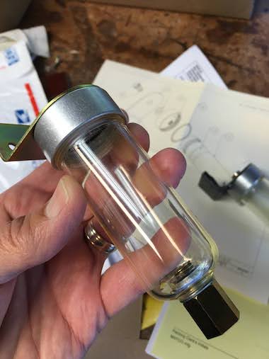
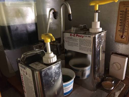 Here is the new EZ-Poxy/87 with the West System pumps and the hose clamp towards the top of the resin pump stem. The EZ-87 hardener was completely crystallized but I put it in a bucket of hot tap water and it became liquid again in less than 10 minutes, per Gary Hunter's recommendation to just heat it up in hot tap water which should be around 140F. One pump from the resin (with the hose clamp) and one pump from the hardener gives the prefect ratio.
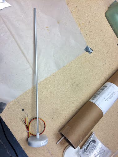
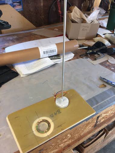
Also shown is one of the capacitance probes from Princeton-Electronics. The portion near the white base is bendable so the aluminum tube will bend up to the top of the tank from the white base that's mounted in the tank sidewall and then down so that the tip is at the bottom of the tank. I plan on following Mark Zeitlin's installation method.
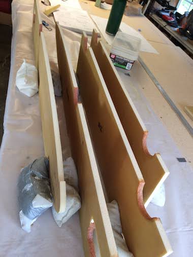
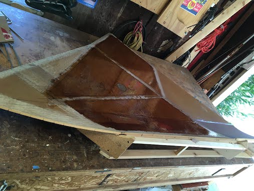
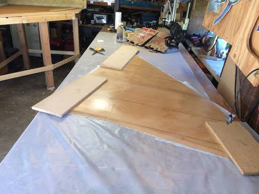
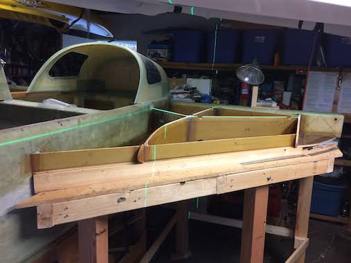
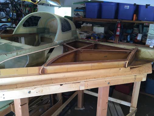
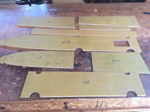 The first task is to build the strake ribs and baffles, some builders lay them all out on a sheet of pvc foam, glass both sides of the sheet of foam and cut them out. I did it old school per the plans and made paper templates then cut them out from the foam over-sized and glassed both side with one ply of BID at a 45 degree angle. Then I used the paper templates to redraw the lines accurately and cut them out on the bandsaw. Bought a new bandsaw blade just for this because they don't last long when cutting fiberglass, surprisingly it survived cutting out all the ribs and baffles. The picture shows one set.
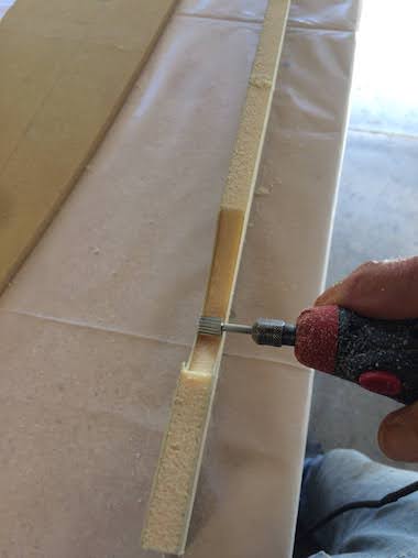
I used a router to cut out the openings and half circles. I also decided to finish off the openings with flox and used a dremel to hog out about a 1/16" of foam and then filled with flox and ground the cured flox smooth. The plans don't require you do finish off the exposed foam openings and half circles with flox since the PVC foam is fuel resistant, however it is recommended in the Builder FAQs because small foam particles can break off and clog the fuel strainer and/or filter. The rest of the exposed foam will be floxed/glassed to the top and bottom strake skins. Working with the EZ-Poxy has been really good, it does have more of a chemical/bondo smell, which I like, Lynn is more sensitive to smells so good ventilation is needed.
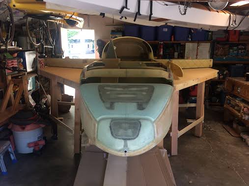
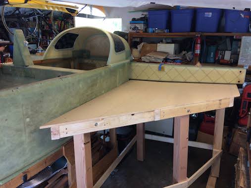
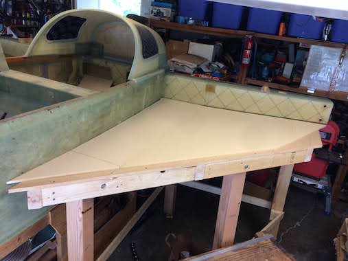
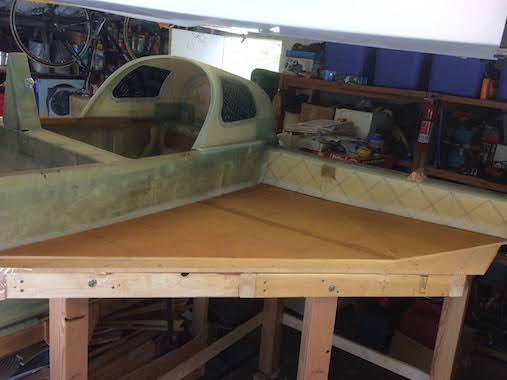
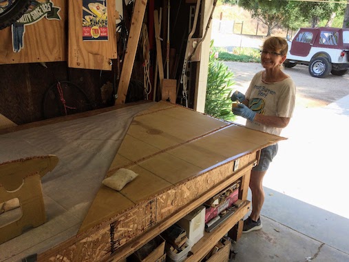
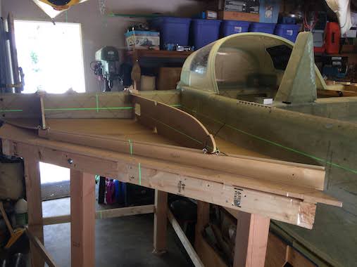
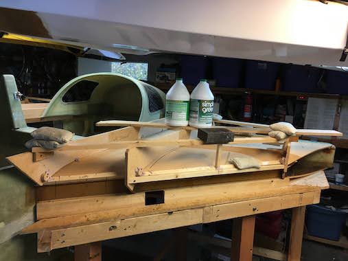
 After the ribs I built the strake tables. I built them the recommended plans size 4'x6' but it was going to be too hard to work around them so I cut them nearly in half diagonally to be a slightly larger than the actual strake size. I also pushed my work bench (glad to have put the swiveling wheels on it) against the garage wall which gave adequate working room around the tables. The table provides a platform to build the stakes, it needs to fit just underneath the center spar and be level forward and aft with the fuselage. So the table is angled laterally with the center spar and level fore and aft with the fuselage at the centerspar inner face. So the fuselage also needs to be level fore/aft and laterally. It's always fun trying to make something level in every possible direction. I put threaded inserts in the table legs to enable fine tuning with the turn of a bolt.
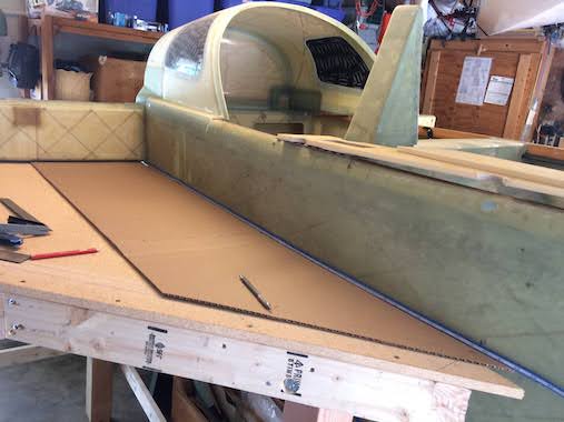
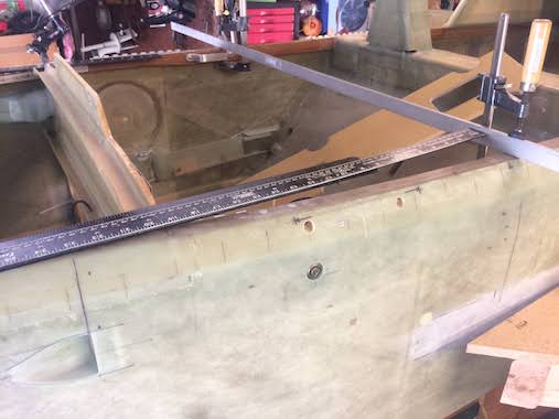
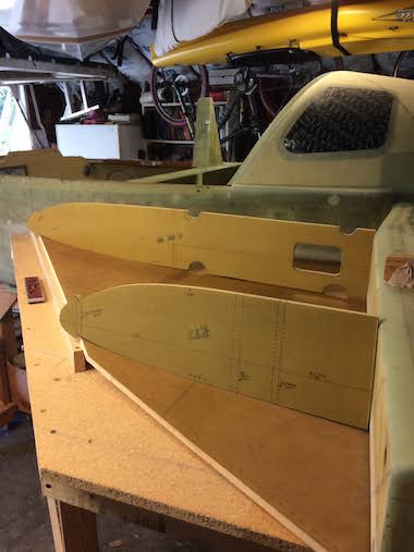
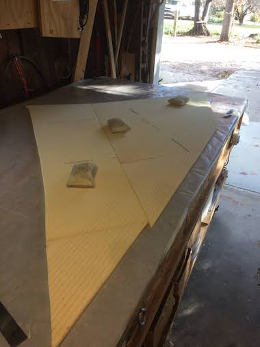
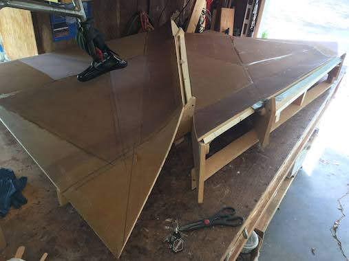
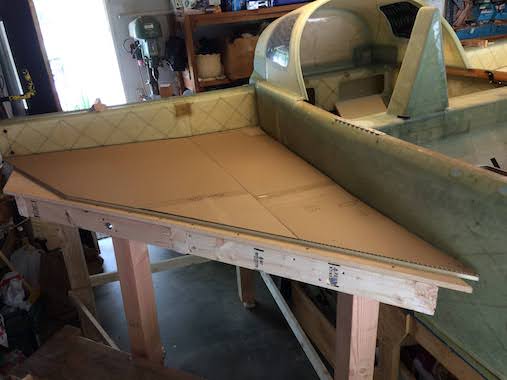 I made inboard and outboard cardboard templates for the bottom skins. The outboard template is the same size for both sides and just flipped over for the opposite side. The inboard templates are unique because they need to conform to the fuselage side which is hand shaped and each side is slightly different. It was challenging to make the templates closely fit the fuselage sides. I first made a paper template with a roll of paper just folded between the fuselage side and the table which provided a rough line. I traced this on the cardboard and cut it out. The cardboard could then fit within a 1/4" of the fuselage side so then I double stick taped a flexible ruler to the fuselage over the top of the cardboard and could draw a line exactly the same as the fuselage side.
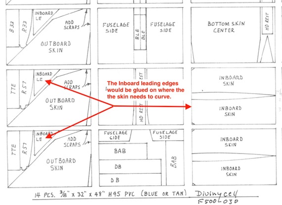
 I was debating how to lay out the templates on the foam sheets because it didn't seem that the plans layout was all that optimal with respect to having to add extra little pieces. I also thought that microing the pieces together would be better than 5 minute epoxy, except that the 5 minute epoxy joints would probably be more flexible. I asked the Cozy email group and the recommendation was to just follow the plans layout and use 5 minute epoxy, which is what I did. The 5 minute epoxy was a challenge on the long joint along the inboard and outboard sections so Lynn helped me with that.
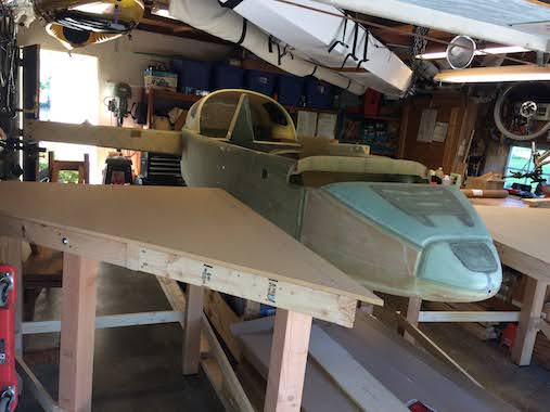
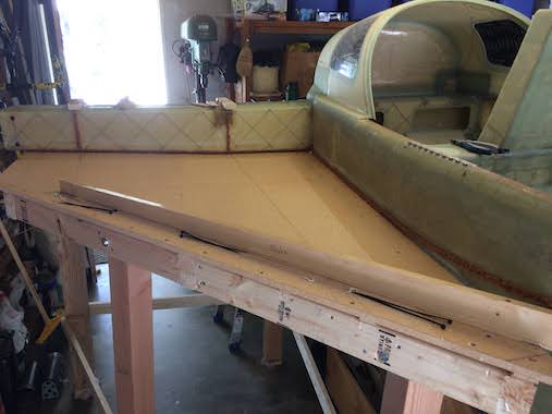
 Before starting anything you need to make sure the fuselage and tables are level in all directions. The tables are are bondo'd to the fuselage side, center spar and to the floor so that it can't be bumped out of position.
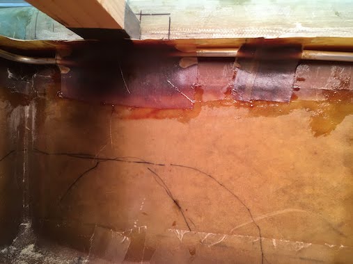
 Here the inside of the bottom skin is glassed with 1 ply of BID at 45 degrees to the leading edge.
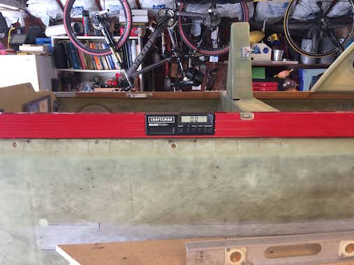
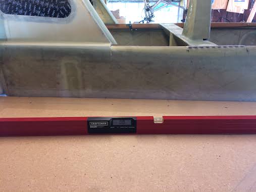
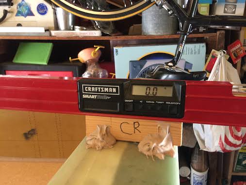
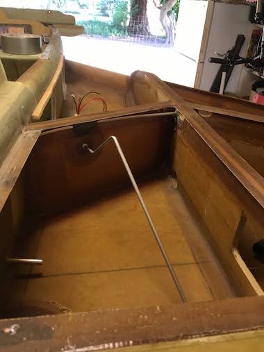
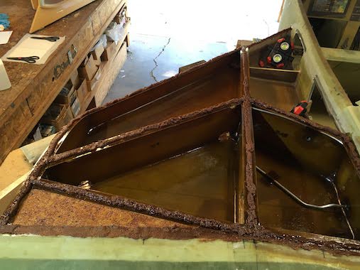
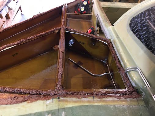
 Fuselage Station (FS) 60 is measured as it is a reference point for the front inboard tip of the strake. Also positioning the ribs to determine if they are level and at the correct 17.4 inch water level.
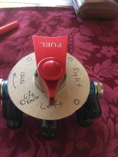
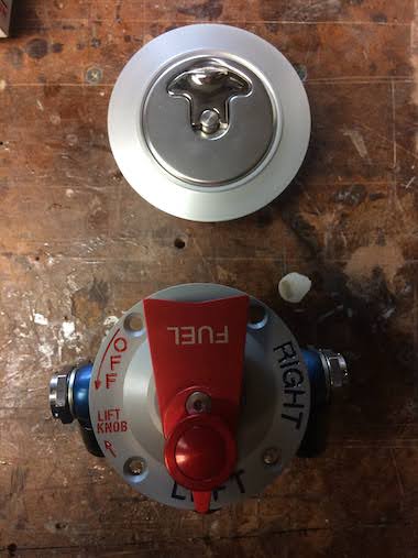
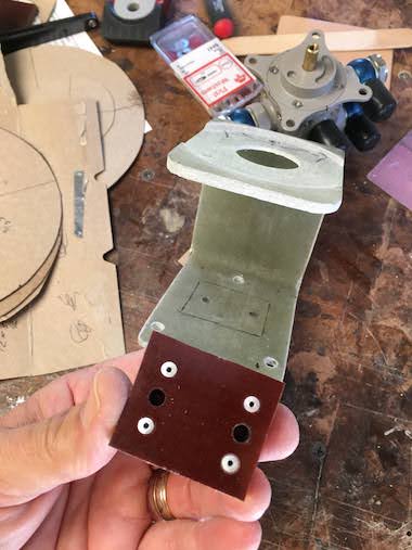
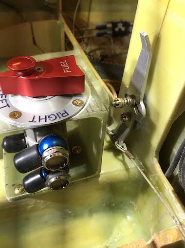
 Realized that the Andair fuel valve fascia plate will not work, the plate orientation is for a front engined airplane, never thought that would matter but the plate can only be installed one way on the valve. Made a mock-up of what I needed and sent to Andair to make me a new one. The button on the top is a safety feature and needs to be lifted to rotate the valve lever to the Off position.

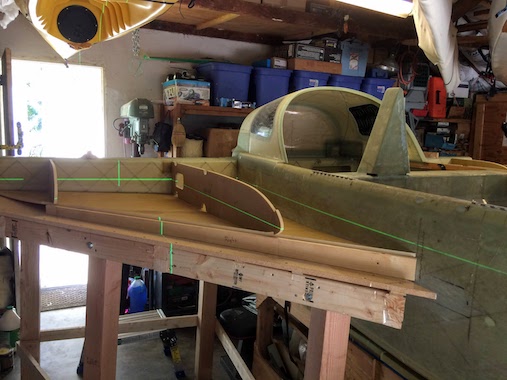
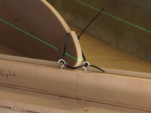
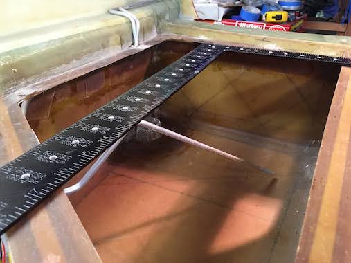
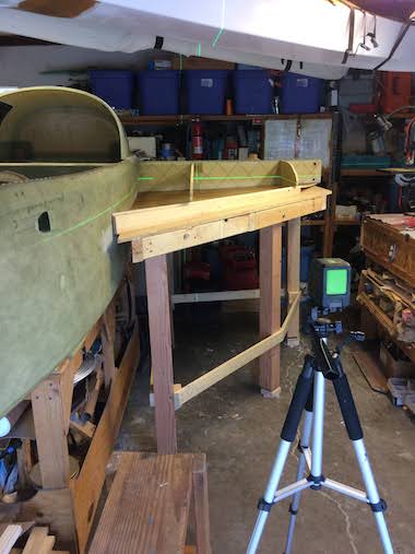 It was becoming really frustrating trying to get the ribs positioned at the correct water level relative to the fuselage by just measuring with rulers and levels. I finally broke down and bought a Huepar Laser Level, there were others that were cheaper or more expensive but this was the only one the specified an accuracy of 1/13" which was way better than what I could do with rulers and levels. I marked the 17.4" water level line on the side of the fuselage at FS 60 and lined up the laser line with that and adjusted the wood strip under the bottom skin leading edge to get the ribs at the correct water level. The laser level mounts to a regular camera tripod to adjust the height and angle. This made it so much easier and repeatable.
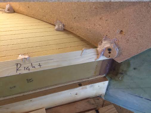
 I bondo'd some wood strips on the center spar to shim the aft end of the ribs in place. Lynn's putting flox on the edges of the bottom skin where it bonds to the fuselage and center spar. I don't have a picture, but the first 6" of the bottom skin foam leading edge is scored spanwise so it will conform to the curve of the rib. It's easy to score a little to aggressively which I did on the right side a bit where you can barely see the score lines through the the one ply of BID of the bottom skin. I will lay up another ply of BID later to compensate for that.
 Used the cake icing method to put flox on the bottom edges of the ribs. Used cup hooks and zip ties to pull the nose of the ribs down on to the bottom skin so that it would conform to the curve of the rib.
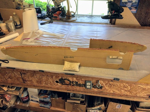
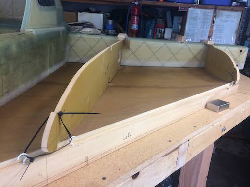 Fit check of the ribs and bottom skin and then finally ribs and bottom floxed in place with laser level check of 17.4" water line. I peel plied the flox fillets to smooth them out and make sanding easier.
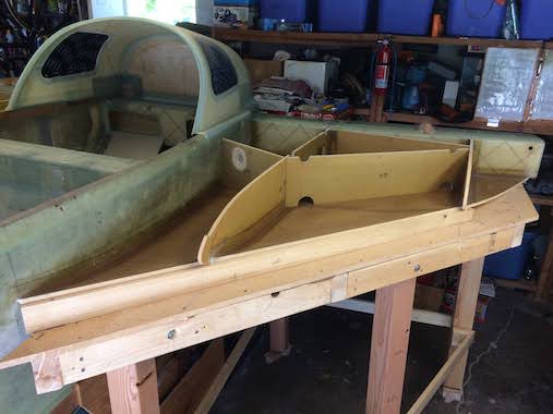
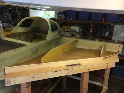
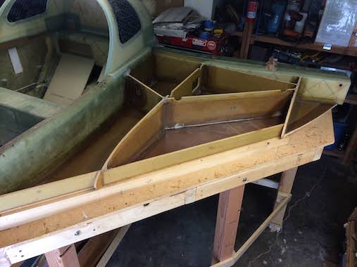
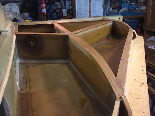
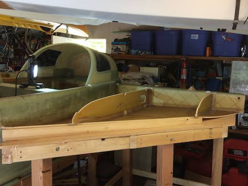 Here the bottom skin is glassed to the fuselage and center spar and the ribs are glassed to the bottom skin and the forward face of the center spar. Starting to position the other baffles in place.
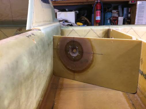
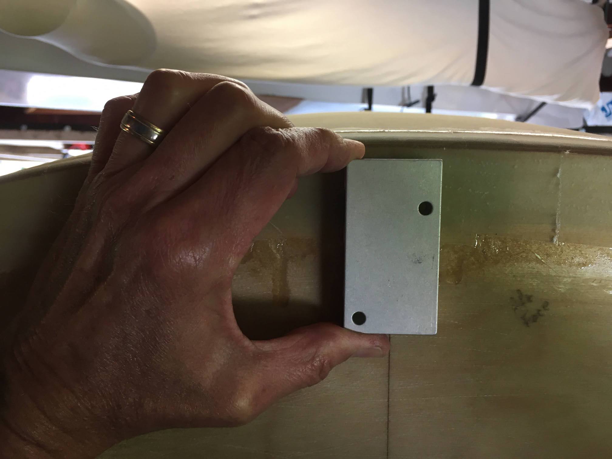
 So I followed Mark Zeitlin's method for the capacitance probe installation. I added a couple of plies of BID to the probe side to make it as flat as possible. In the first picture you can see how the SAE flange is embedded in the baffle. It was a bit tedious opening up the holes after floxing and glassing in the flange. The threaded holes do not go all the way through so I added another couple plies of BID on the tank side so that if someone inadvertently put screws in that are too long it won't bust through the inside of the tank without quite some effort. I still need to bend the probe to fit into the tank but will wait until I'm done with all the glassing.
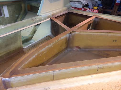
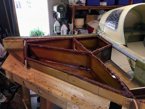
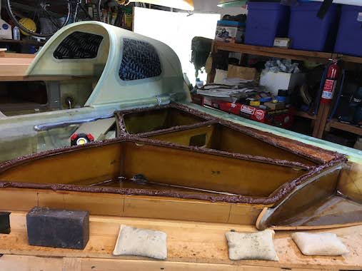
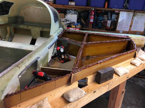
 So we finally have all the ribs, baffles, trailing and leading edge tank walls floxed and glassed in place. This took a lot longer than expected, each piece was first floxed in place and allowed to cure, sanded then glassed with 2" wide BID tapes. This required a lot of sanding in-between steps. I did most of the baffles and trailing/leading edges one at a time because it's hard to hold all of them in place at the same time as the plans would have you do.
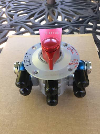
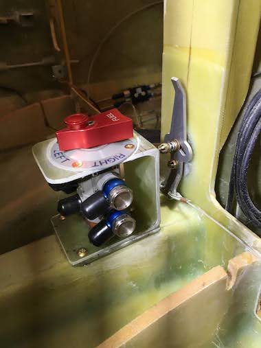
I also got the new fascia for the Andair duplex fuel valve so that it can point in the correct fuel tank positions, sort of. Because the valve switches tanks in only 90 degrees of lever rotation I will have to have the left tank position point directly aft and the right tank position correctly pointing to the right, I don't think this will be too confusing. I also purchased new Newton lockable fuel caps also from England like the Andair valve, and also pricey, but both are very nice quality. The fuel caps specified in the plans are very robust but the finish was very crude, I was able to return them to Aircraft Spruce and applied the credit to the Newton caps.
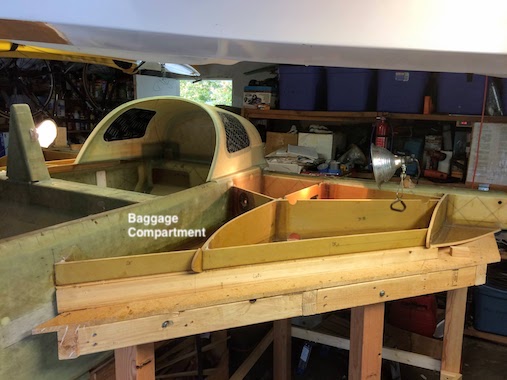
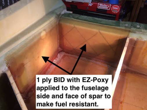 To make everything as fuel resistant as possible I applied one ply of BID to the fuselage side and forward face of the center spar with EZ-Poxy. The forward strake section along the fuselage will be a baggage compartment and not exposed to fuel.
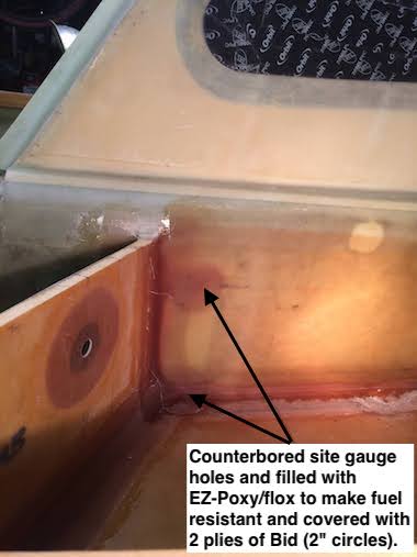
I also counter bored the fuel site gauge holes about 1/4" dia. to the depth of the white backing plates floxed on the inside of the fuselage. I filled the holes with EZ-Poxy/flox and covered with 2 plies of BID (2" circles) to make them fuel resistant.
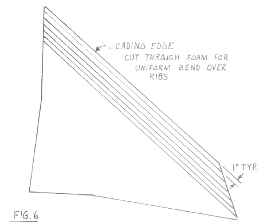
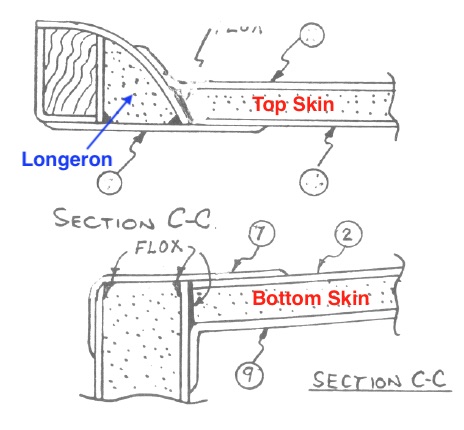
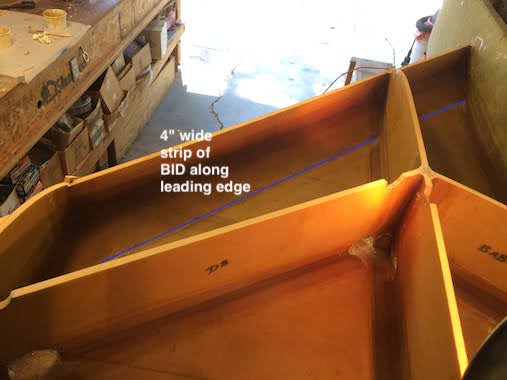 As mentioned earlier I added a 4" wide strip of BID to the leading edge of both strakes to primarily address the score marks that were visible on the right strake. Other builders recommended strengthening the leading edge as well due to scoring the foam. Sketch from the plans showing the score lines of the strake leading edge.
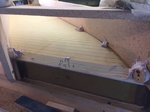
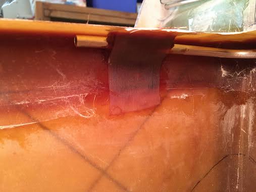
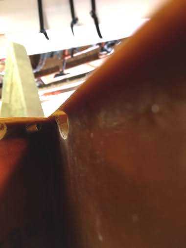
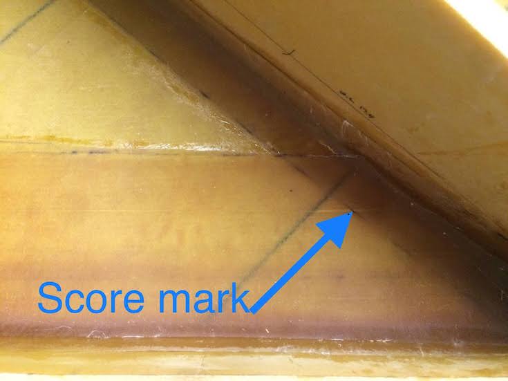 Here you can see the light score mark, the white streak running left to right. The one ply of BID has already been added over the top, just to be sure there are no leaks.
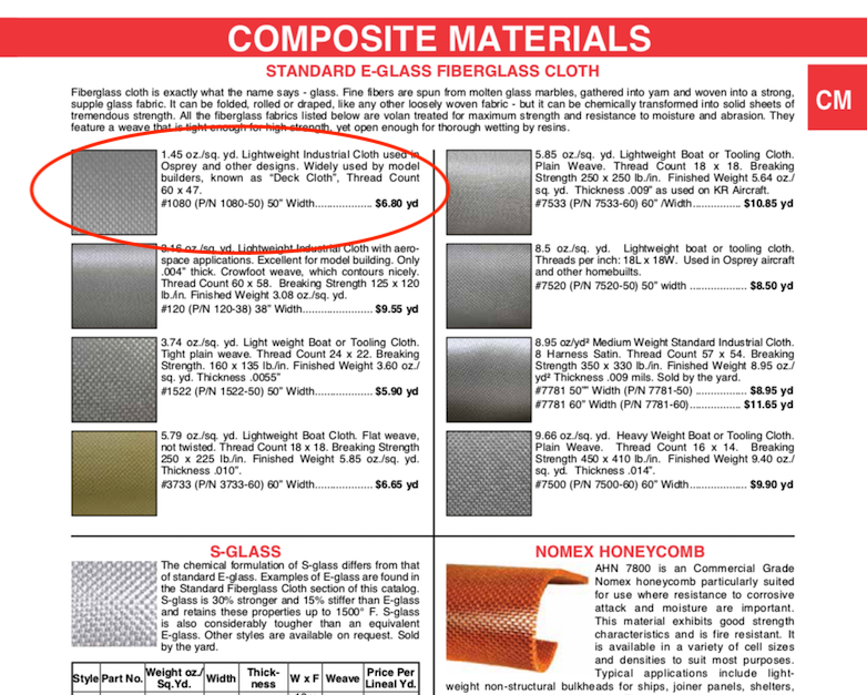
 So I got all the ribs, baffles, leading and trailing edges taped with 1 ply BID to the bottom skin and each other. As further protection against leaks I laid up a single ply of 1.45 oz/sq yd deckcloth over the bottom and the sides of everything. The cloth is quite thin but it still turned out easier to wet out between two plies of thin plastic, I used painters drop cloth plastic which is a bit wrinkly but still worked for this. It really soaked up the epoxy so it was better not to paint the bottom or sides before applying it. Put peel ply over the deckcloth. Left a 1 inch border along the top of the ribs, baffles, trailing and leading edges without deck-cloth so as not to degrade the bond for the "T" Hats later.
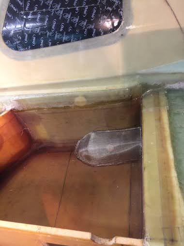
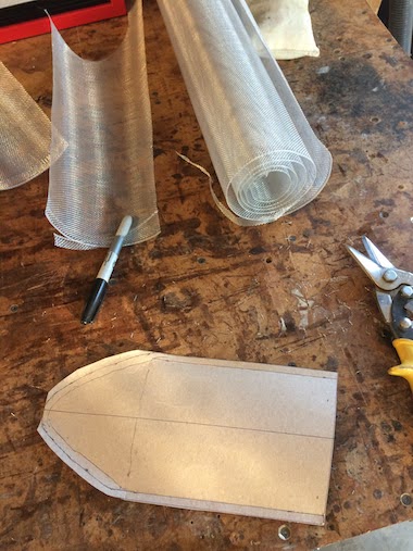 I thought I'd get started on the fuel strainers. I was planning on using the straining colanders that other's used but I couldn't find any that assured me that it was made of a quality USA made stainless steel. So I kept with the plans method of aluminum window screen material. The local hardware store had a large roll for about $6.00. I didn't think it was going to be so hard to cut out a piece that would work but I was starting to deplete the roll quite quickly with rejected pieces. Finally decided to make a template, and was able to cut out a shape that would work. When all else fails make a template. I didn't flox them in place yet because with all the fiberglassing that would need to be done in the area I thought they might get mucked up with epoxy and flox. So they're ready to go on just before putting on the top skins.
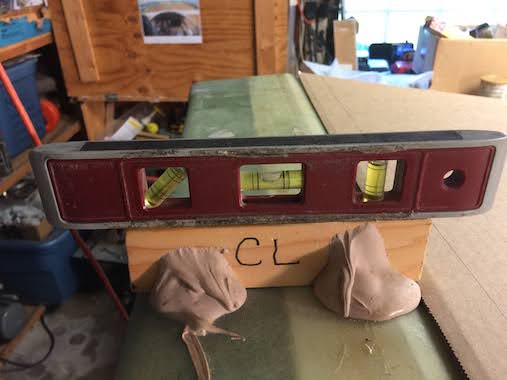
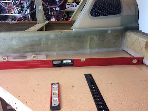
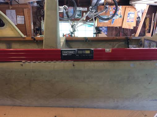
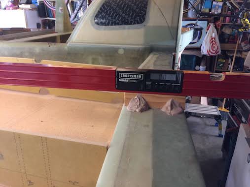
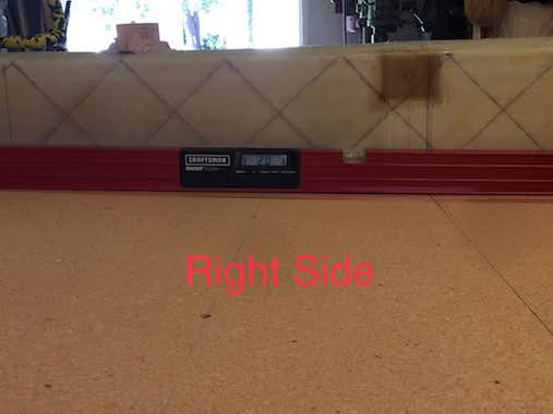
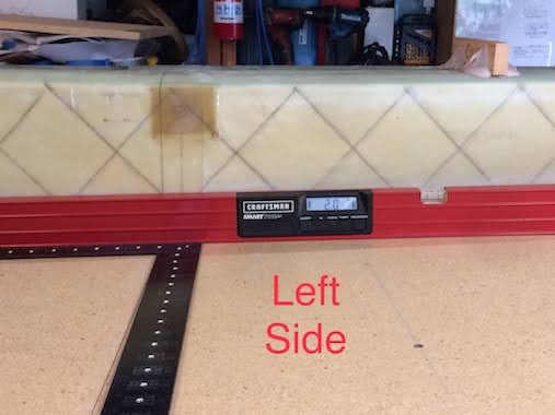
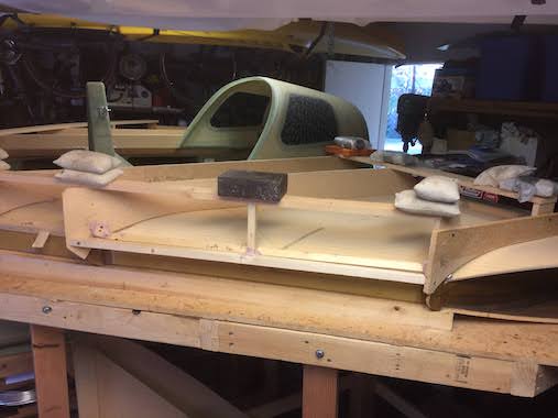
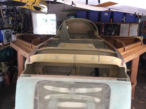
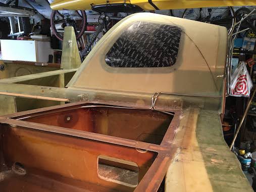
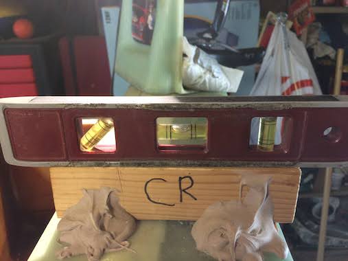 In preparing for making the top skins I realized that the level blocks on top of the center spar would have to be knocked off, so some last pictures showing them level with the fuselage being level.
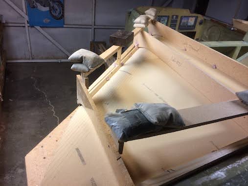
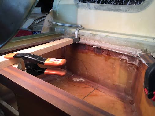
 I made 2 ply BID ledges along the aft inboard corner of the strake. I five minute epoxied some foam with the bottom flush with the top of the ribs, center spar and BAB baffle and covered it with duct tape. That way I could make a corner that was taped to the fuselage side and face of the center spar. In the pictures below you can see how I used the lazer level to draw a line level and flush with the tops of the ribs and baffles.
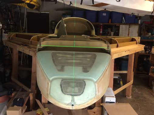
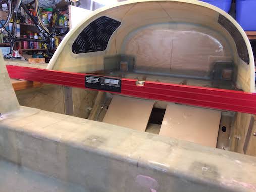
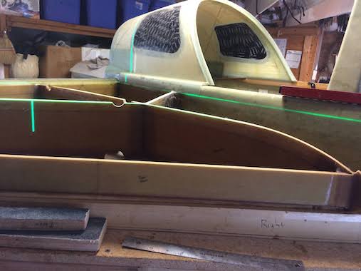 The amazing lazer level at work here projecting a level line along the fuselage side at the same height as the tops of the ribs, baffles and center spar beveled edge. Earlier I had trimmed the top of the ribs and baffles to make them level, they were slightly high in the front. The plans say to check this by laying the tops skin on and put a level on that, to make sure the ribs and baffles are level or slightly low in front. So much easier to do it with the lazer level since I hadn't started on the top skins and I wanted to cut out the baggage compartment access holes and for that you need to know where the bottom of the top skin will be. For kicks I set up the lazer level down the center line of the fuselage to see how things lined up, I was really amazed everything lines up pretty well within in a pen line of each other.
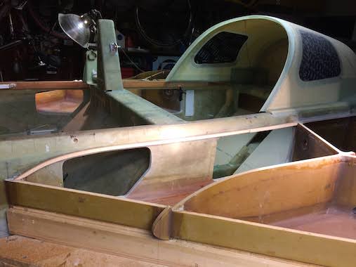
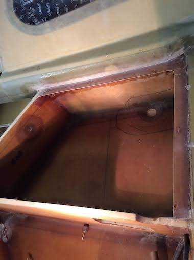
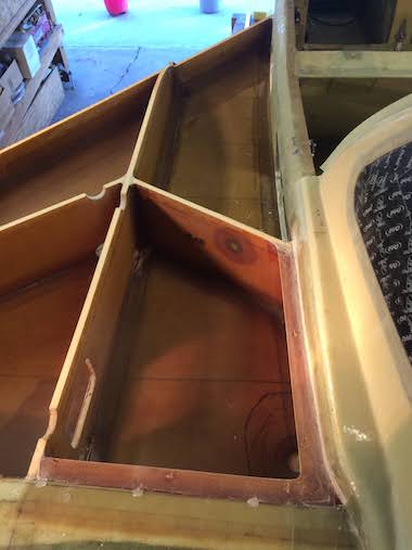
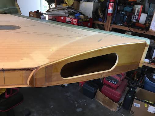
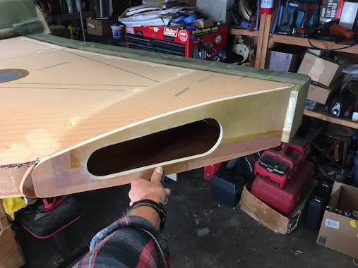
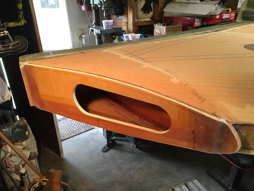
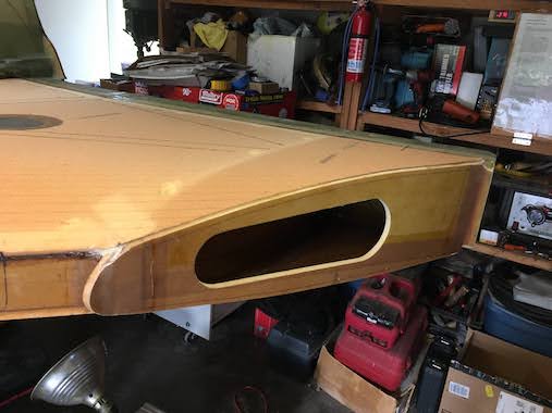
 The first picture (left) shows crude cutouts of the baggage compartment access holes. The right pictures shows the nearly finished access holes, with a foam strip 5 minute expoxied to the fuselage side to support the top skin. I made templates of the baggage compartment cutouts so I could see where the cutout would be on the inside of the fuselage and make sure I didn't cut through the seatback or any other important structure. I made two holes in the templates, taped them to the plans location on the outside of the fuselage and drilled the holes through the fuselage and then was able to line up the template on the inside wall of the fuselage to see where the cutouts would be. This really helped because even though I did much of the cutting with the Fein sander the corners had to be down with a Dremel/flex shaft and a Roto Zip bit for clearance with the seat back. It was also a bit nerve racking to cut the rear cutout flush with the BAB baffle. It took me a couple of days to make the cutouts without damaging critical structure.
I was really confused by the cross section C-C views of these cutouts in the plans Chapter 21, Page 3. It didn't dawn on me for the longest time that the upper cross section view was for the top skin and the bottom view for the bottom skin. And the light bulb really clicked on when I realized that the baggage compartment cutout would not only be flush with the bottom of the top skin (which is written in the plans) but also with the bottom of the longeron. I really wish they would have written that in the text of the plans that the top strake skin bottom should be flush with the bottom of the fuselage longeron. Also to label the top and bottom skins in the C-C cross section view. As luck would have it (or just blindly following the plans not knowing what I'm doing) the lazer level line I had projected along the sides of the fuselage flush with the tops of the ribs, baffles and center spar ended up flush with the bottom of the fuselage longeron. I know Someone is watching me from above to make sure I don't mess up too bad. It was also a bit difficult to determine the downward arc from the level line to the strake leading edge. I followed the plans method of using a long straight edge and running it along the tops of the ribs and against the side of the fuselage and marking it but since the ribs are swept back it's not really possible to have the straight edge perpendicular to the fuselage, so I made some marks and with that I took a piece of 3/8" foam a 1/2" wide and tried to bend it along the marks I made and make a smooth pleasing arc. Not sure if the top skin will be able to bend to that arc while also bending down to the ribs and leading edge, we'll see, may have to modify it later.
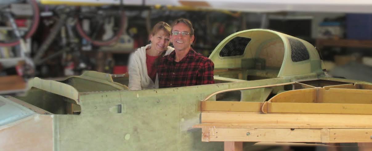 It's Christmas 2021, a new COVID 19 variant is brewing, they call it Omicron, sounds like some new tech start-up. Anyway here's one of the pictures from our Christmas card. Did some photography shenanigans by blurring the background. I use a Mac and don't have any real photography manipulation apps but Googled how to blur the background and found a way by just using the Preview and iMovie apps. Blur the picture using iMovie and save it with a different name, then laso the portion of the picture you want in focus using Preview and paste it over the blurred picture, it's a little hokey but not bad. Next year I think I'll paste us flying over the mountains.
Wishing You a Merry Christmas, Happy Holidays and a Happy New Year!
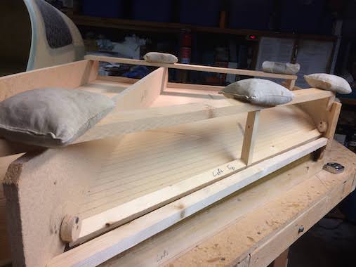
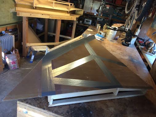
 So the next step was to make the cap strips (T-Hats) on top of the strake ribs for better bonding of the ribs to the top skins, which meant making the top skins. I used the same technique as with the bottom skins to get shape of the fuselage on in the inboard foam panel and 10 minute epoxied the panels together, using the hinge method. I don't have any a pictures but then the bottom side of the top foam skin is microed and glassed with 1 ply of BID oriented 45 degrees to the leading edge. For the top skins I scored the leading edge at 1/2 inch spacing as recommended in the "Builder's Hints". Next I built a wood frame work to hold the foam skin down on the ribs. I used scrap pieces of particle board from the support table. To get the shape of the ribs on the particle board ribs I just used the original rib templates and accounted for the thickness of the foam with a 3/8" spacer block, running a pencil against the spacer along the rib template line.
 The hard part was to get the skin leading edge to conform to the curvature of the rib leading edge. So with a hole saw I cut out several paricle board wheels then drilled an off center hole and screwed them into the particle board strategically to be able to wedge a strip of wood down on the leading edge of the skin. With that I could get close contact of the underside of the skin to the rib and bondo the top skin to the wood frame.
 Really didn't take much pictures of creating the cap strips, but followed Wayne Hicks Cap Strip Method. Basically what I did was put two plies of duct tape (similar in thickness to two plies of BID for the cap strip) on the glassed bottom of the top skin wherever the ribs and bulkheads would make contact with skin. Then I piled micro on top of the ribs and bulkheads and put the top skin with the wood framework down on top of the ribs/bulkheads. This step fills any gaps between the ribs/bulkheads and bottom of top skin and I let it cure. I then popped off the skins and cleaned up the micro by sanding the excess along the sides of the ribs and bulkheads. Now the tops of the ribs and bulkhead are an exact match with bottom of the skin.
 So now with the top skins off I pulled of the duct tape and replaced it with clear packing tape since it's much thinner. I lightly sanded the micro on the tops of the ribs and bulkheads for a good bond. I layed up 2 ply BID tapes 1.5 inches wide (Builder's Hints say 2" wide and Wayne Hicks did 1" wide, so I compromised and thought 1.5" seemed good) over the packing tape, I did put peel ply inbetween the packing tap and the 2 plies of BID so that the top of the cap strips would be easy to sand. Don't put the peel ply on top of the BID tapes or the peel ply will end up inbetween the top of the ribs/bulkheads and the cap strip and you won't have a good bond. It gets confusing because when you're laying down the BID tapes the skin is upside down. I also didn't overlap any of the tapes otherwise you'd have 4 ply bumps. I was able to make them single length tapes that butted at intersections, I figure that the bond with the top skin will tie them all together. I then put the tops skins back on, weighed it all down and let it cure. After cure it was a real pain to pop the skins off, in this case slowly prying at the outboard edge where there's an edge to grip on seem to work as opposed to bumping it apart. There was some flexing so some of the bondo blobs broke loose but slowly and carefully I was able to get the top skins off and rewarded with nice cap strips on top of the ribs and bulkheads. Then it was the very time consuming task of laying up a ply of BID in the corners of the cap strip and ribs/bulkheads.
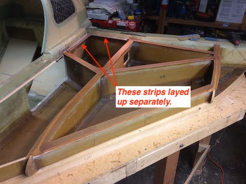 I should mention that in the rear inboard corner formed by the fuselage and the center spar leading edge those strips were layed up separately prior to the cap strips. I five minute epoxied some foam strips in place with the bottom edge of the foam level with the top of bulkhead and ribs and covered with duct tape. I put a flox fillet in the corner and layed up 2 plies of BID on the underside of the duct taped foam strip overlapping onto the fuselage wall and face of the center spar. After cure I pulled off the duct taped foam strips. The plans don't mention doing this, Wayne Hicks thought he might of missed something in the plans, but it's pretty obvious that this needs to be done.
 One important apsect of the strakes is that they don't leak and the plans have you brush on a couple coats of epoxy to seal any pinholes in the layups. Gary Hunter our epoxy guru recommended instead of several coats of epoxy, which could flake off over time, to layup a light weight "deckcloth". So I followed that advice and layed up 1.45 oz deckcloth from Aircraft Spruce it has a very tight weave. I layed that up on every tank surface and also on the inside of the top skins, but not where the cap strips would bond. It is very thin and I found it easier to layup by wetting out inbetween to layers of thin plastic, I used painters drop cloth. Even though drop cloth plastic is a bit wrinkly it still worked good in getting the thin deckcloth wetted out and placed where I wanted it. I also peel plied over the deckcloth. Do not peel ply the deckcloth as I discovered later, see below. You want a wet deckcloth layup.
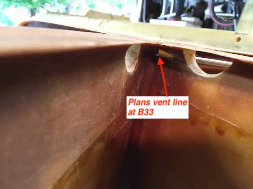
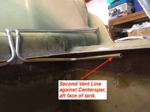
 The next step is to install the vent lines, they are made of 1/4" OD (.035 W) 3003-0 aluminum tubing. The plans only specify one vent line (per tank) that starts just outboard of B33 and runs back over the center spar and out the firewall. It is highly recommended however to have a second vent line at the back of the tank against the center spar. Without the second vent, if the tanks are nearly full the plans vent will be submersed in fuel when the plane is parked nose down, and if it's warm, expansion of the fuel vapors in the tank will force the fuel out the vent. The second vent at the back of the tank will provide venting of the fuel vapors since it will not be submersed in fuel with the plane parked nose down.
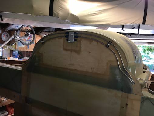
Here you can see how I routed the plans vent line, I kept it under the cap stips.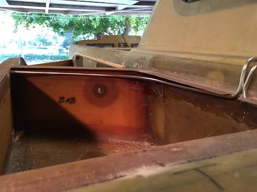
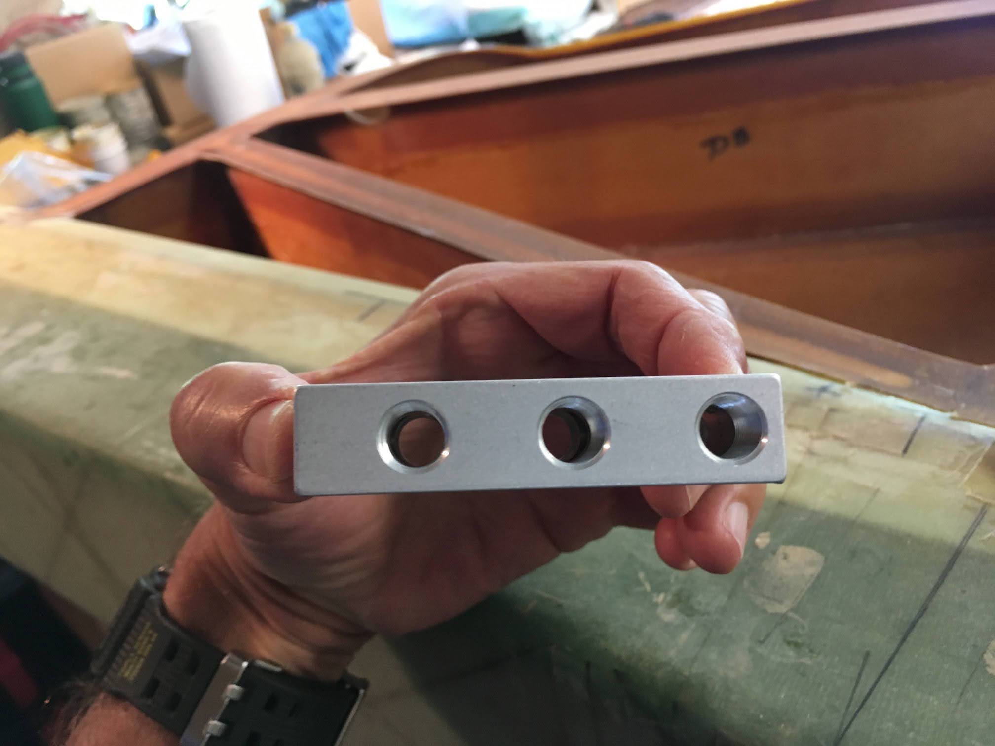
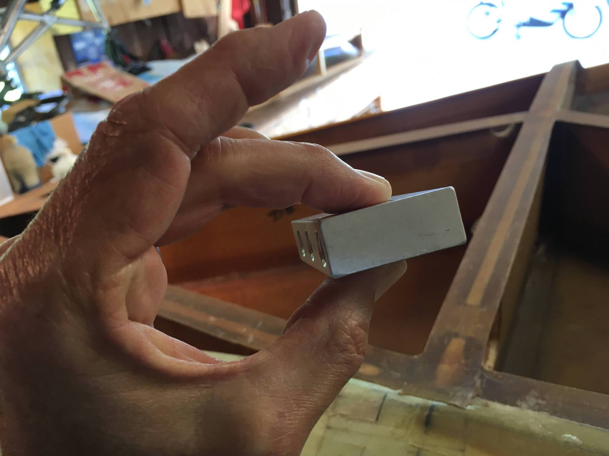
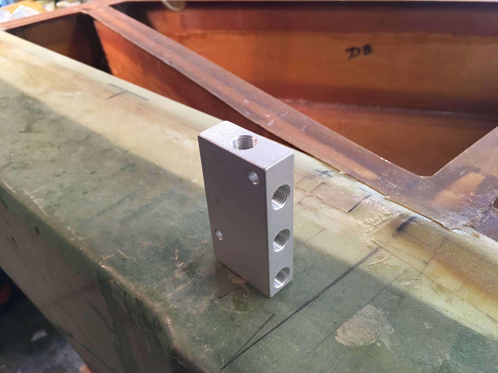
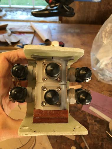
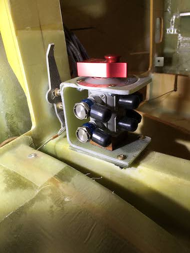
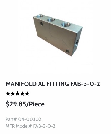 The vent lines are routed up to the top of the firewall and plumbed to a manifold, two in from each tank and then one out from each side that will run down the firewall and underneath the strake. Routing up and over the the canopy will keep fuel from leaking out in case of flipping over in an off-field landing. This is the manifold I got from Aircraft Spruce, all six ports are tied together by a central port drilled through the bottom, which needs to be plugged.
 I mounted the manifold and some adel clamps to the firewall with some extra long Click Bonds to account for the thickness of the fiberfrax insulation and metal barrier. I flared the tube ends and attched the lines with the appropriate AN fittings.
 With the vent line routing complete I floxed/glassed them in place.
 I had to make a cutout in the strip along the fuselage to accommodate the vent lines exiting the tank so I heavily floxed and glassed the underside to make a leak free penetration.
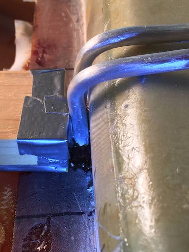
 I used a piece of wood to push the vent lines against the fuselage as close as possible which also served as a flat surface for the flox to cure against. Sometimes you get lucky with how things workout.
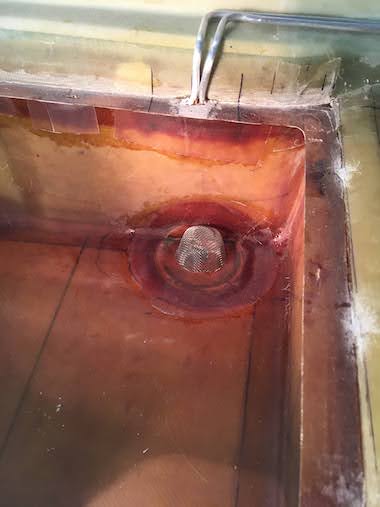
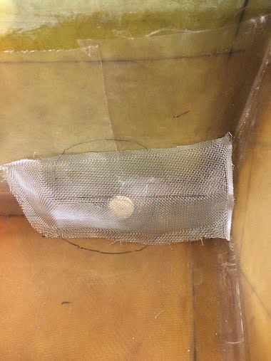
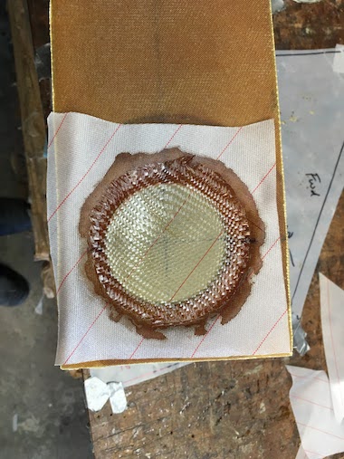
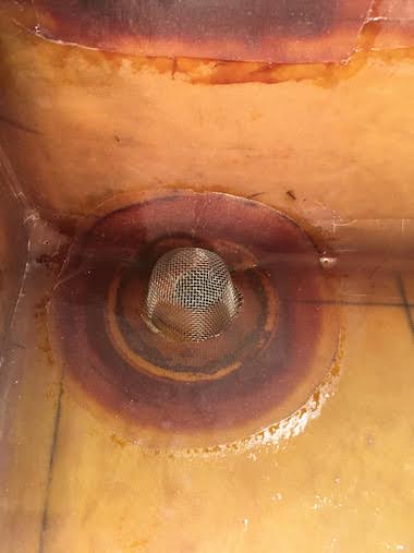 Even though I spent a lot of time shaping aluminum screen material to form the tank strainer, in the end I purchased a stainless steel sink strainer from Amazon. I was concerned that the aluminum screen would hold it's shape and could collapse. With the stainless steel strainer I bend up one edge and glassed it over the tank drain hole. For some reason the picture looks like I got epoxy on the screen but it's really the hole that's covered up below the screen.
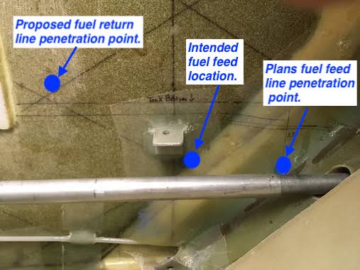
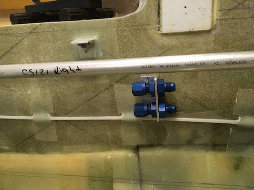
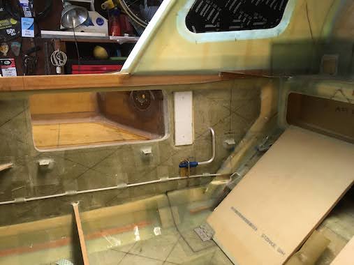
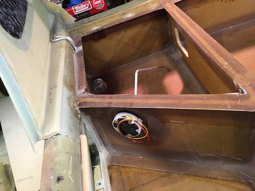
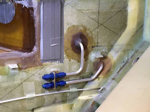
 Trying to figure out where the fuel feed and fuel return lines should penetrate the fuselage wall. I put the fuel return line as shown in the picture and after emailing the Cozy group I put the fuel feed line in the middle position. Marc Zeitlin explained, what is shown in the plans is a figure taken from the Long EZ plans and doesn't reflect the foam doubler that the Cozy has. Marc thought either location would be fine, so I went with the middle position since it gave me more clearance from the aileron torque tube which runs through there. It also gives the same distance from the bottom of the tank so that the tank sump will not need to be any bigger.
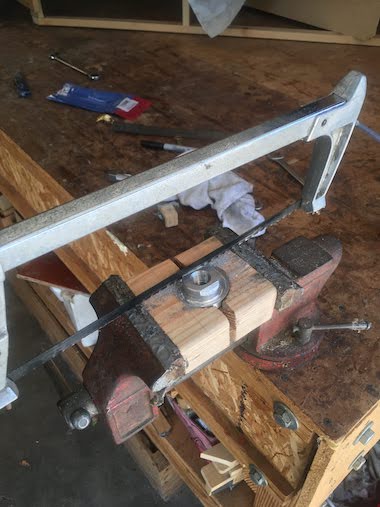
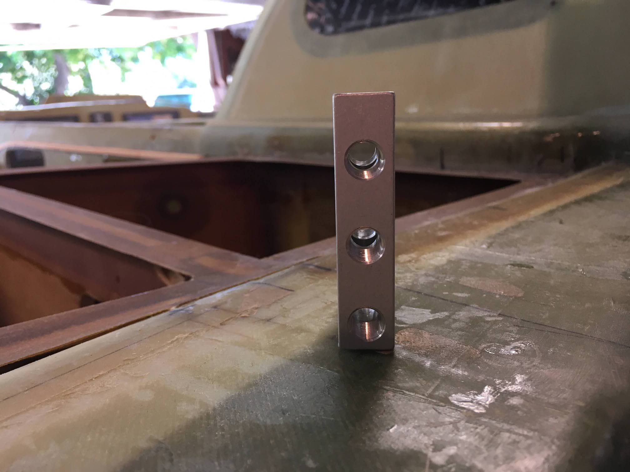
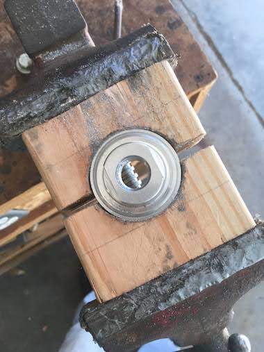
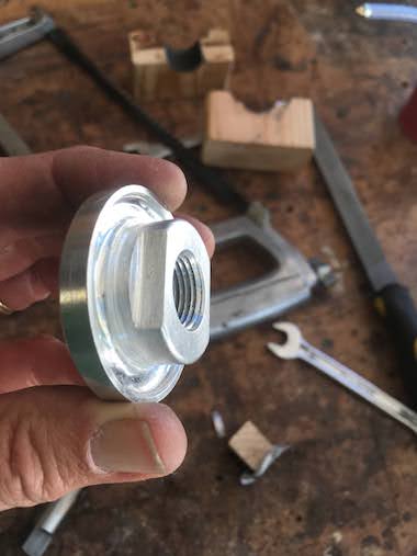
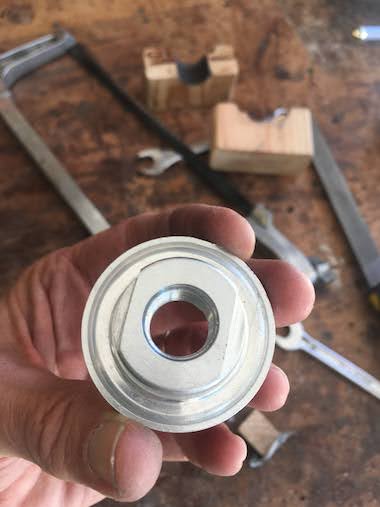
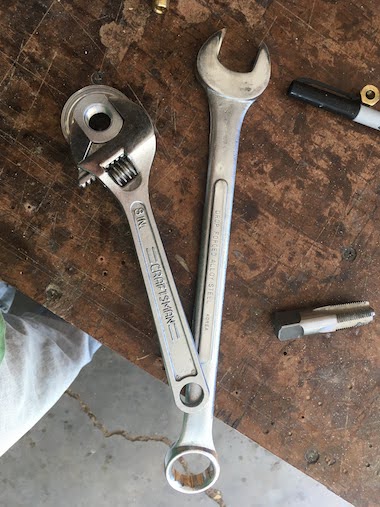
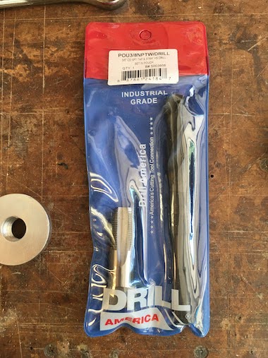
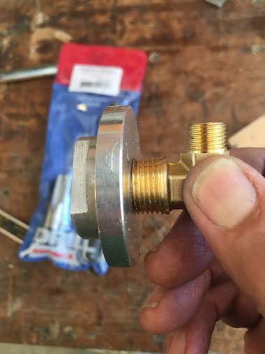
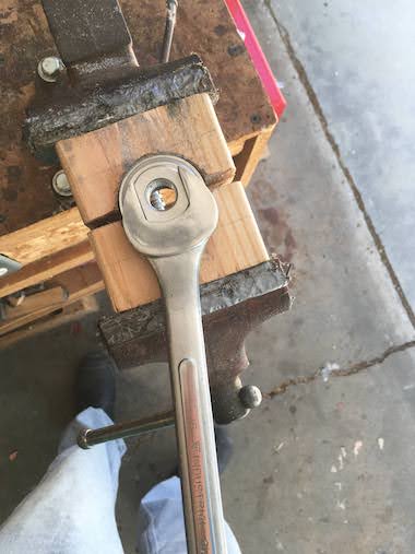 For the fuselage wall penetration I was considering these aluminum tank weldment flanges. I cut some flats on the flanges so that you could put a wrench on it when tightening the tube fittings. It wasn't too difficult just with a hacksaw. It was also necessary to thread the back side of the flange for a tube fitting on the inside of the tank. It required a 37/64" drill bit and 3/8" NPT tap which I bought from Amazon for $9.00. In the end I decided not to go this path, I was concerned that the pipe threaded joints would leak. I don't have great experience with home plumbing repairs. I think this approach is great if you need to put a return line into a tank that is already closed up. Since I have access to the inside of the tank I just drilled a hole through the fuselage put the pipe through and floxed and 2 ply BID taped both sides as you'll see later. I thought this would be my best chance of not having leaks.
 I made some brackets to anchor the fuel lines to the fuselage wall near the penetration point.
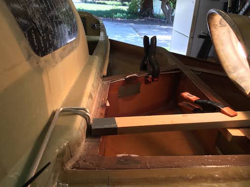
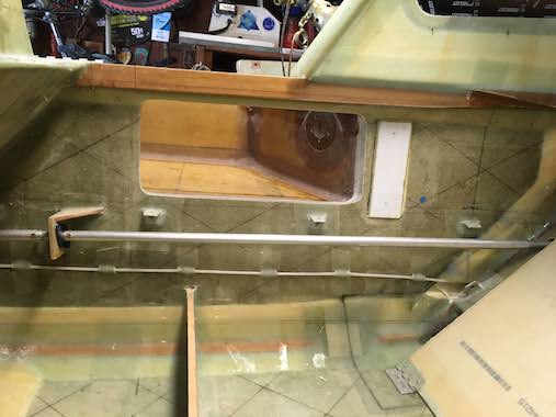
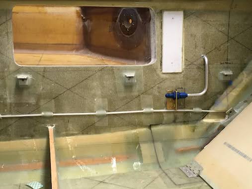 Trying to get an idea how to route the fuel return line.
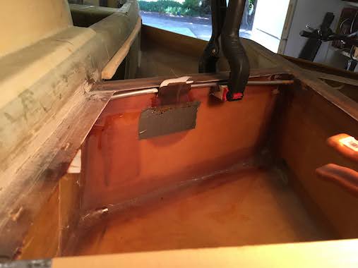
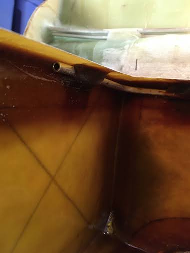
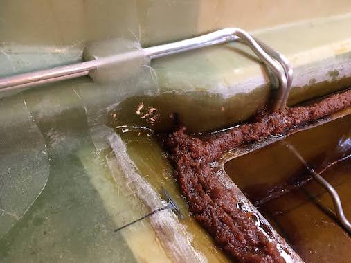
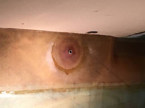
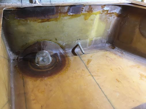 This is where the fuel return line penetrates into the inside of the fuel tank. The fuel line will be longer than what's shown here so that it will be further away from the tank feed hole (where the strainer is). The fuel return line needs to be at least 4" from the fuel feed so as not to feed warm return fuel back to the injection system.
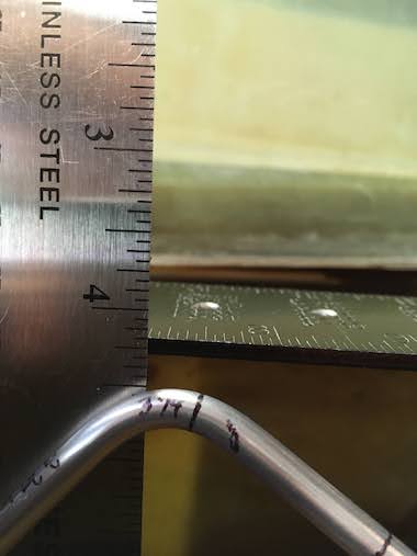
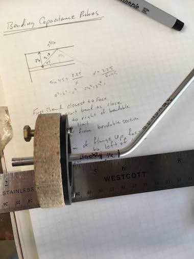 I wanted to see where the fuel quantity capacitance probes would be so that I didn't route the return line in the same spot. I made a mock up of the capacitance probe so I could practice how to bend it. I still ended up bending one wrong but could luckily rebend it. The probe needs a 1/4" clearance from the top and bottom of the tank.
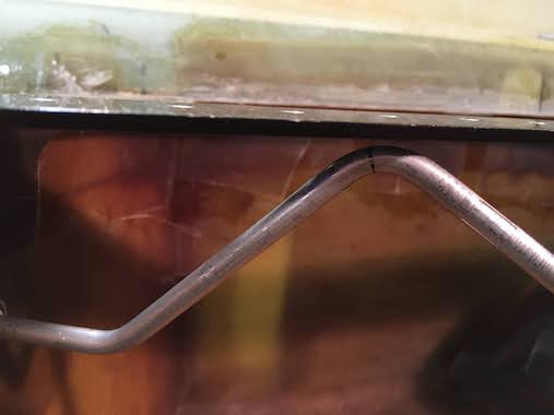
 Here is the actual bent capacitance probe as it would be in the tank.
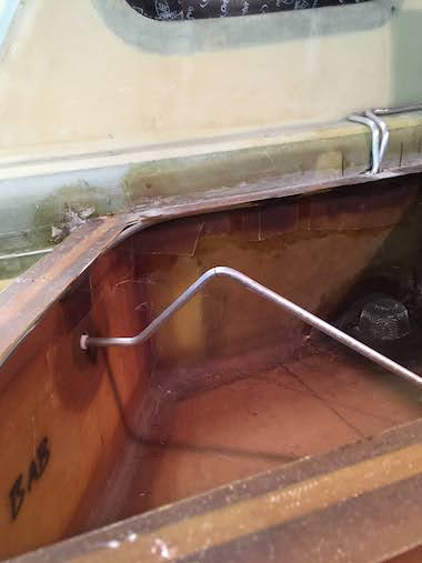
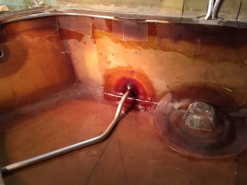
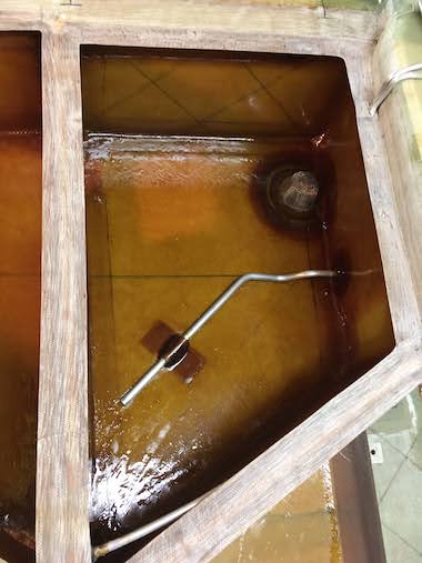
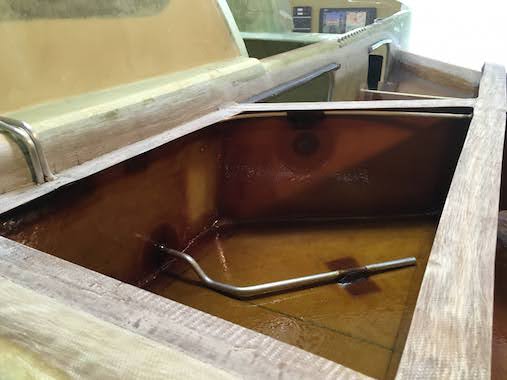
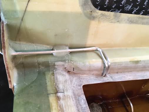
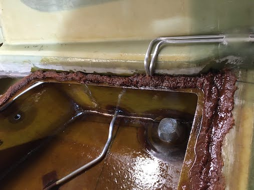
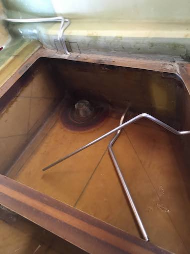 Here I've routed the fuel return line along the bottom of the tank. You can see that it is clear of the capacitance probe and far away from the fuel feed (screen) hole.
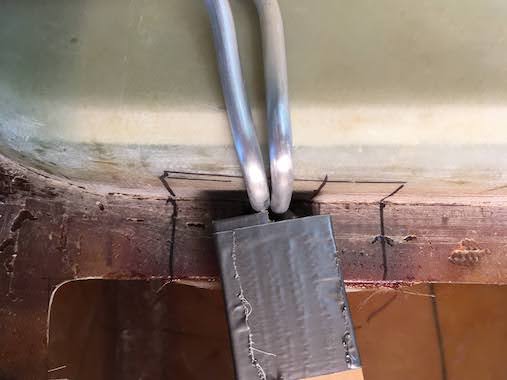
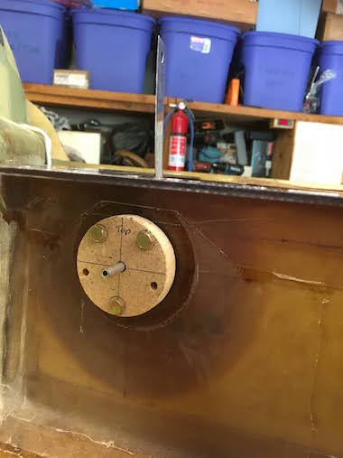
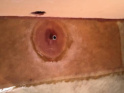
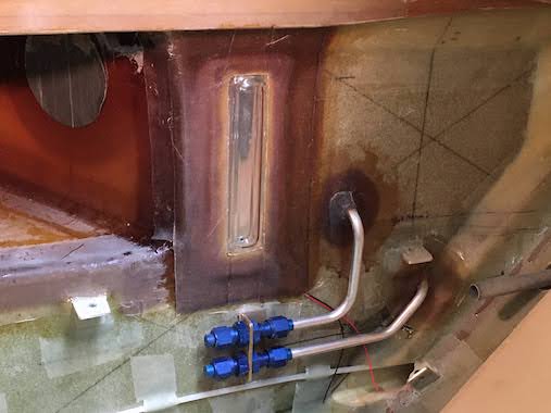
 Here is the interior side of the capacitance probe. So once everything was checked I floxed and 2 ply BID taped the fuel return lines on both sides of the fuselage wall.
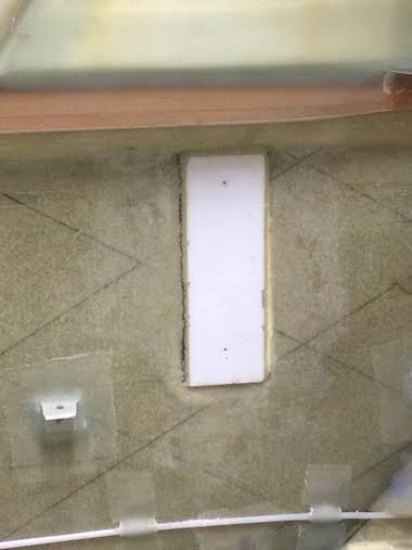
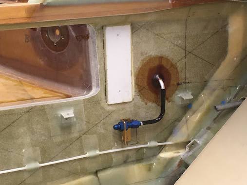
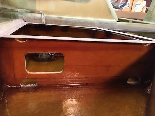
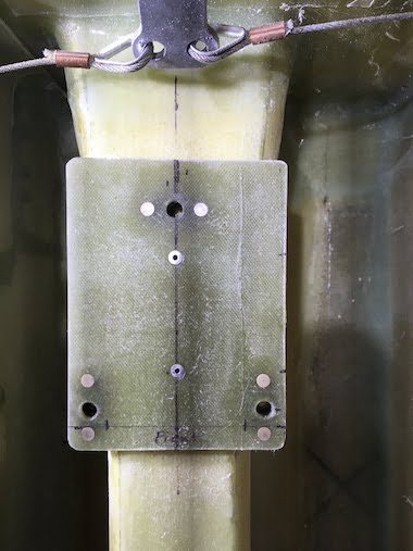
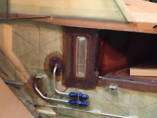
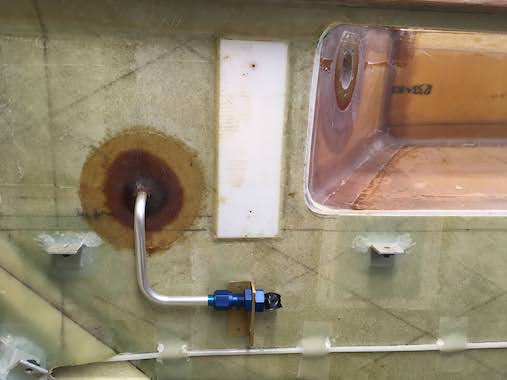 Here is the left side. The white plate is the base plate for the fuel sight guages.
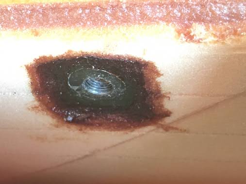
The front corner of the tanks have a quick drain that's used to check the fuel for water or any contamination during the preflight. So a 1" square, 1/4" thick piece of aluminum with a threaded hole is floxed in place there. I made a little wood bridge so I could hold the piece of aluminum in place with a wood screw while the flox cured.
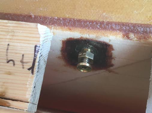
 In the corner I glassed in a little foam ramp to ensure the threaded hole is at the lowest point.
Here you can see the quick drain temporarily threaded in the hole.
In the corner I glassed in a little foam ramp to ensure the threaded hole is at the lowest point.
Here you can see the quick drain temporarily threaded in the hole.
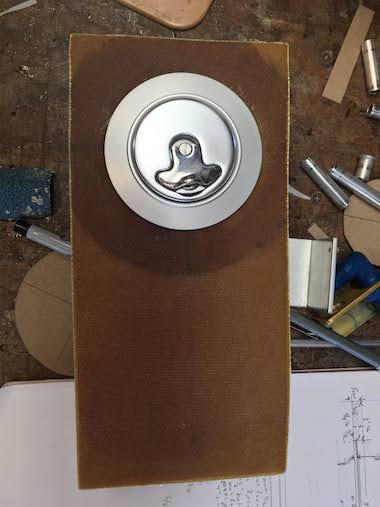
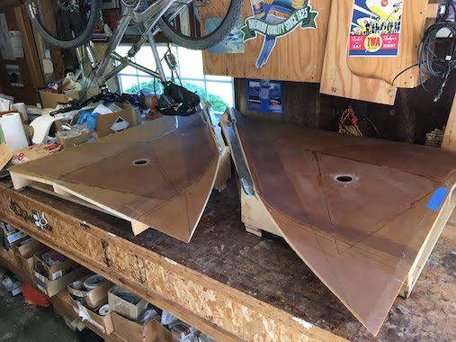
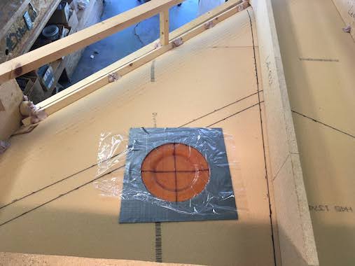
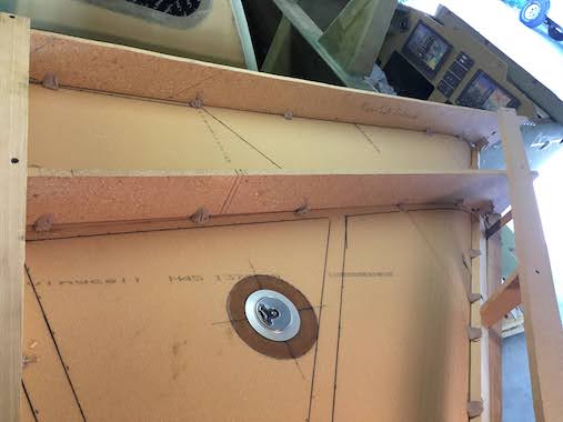
 I made a little mock up of the hole for the fuel cap. I wanted to cut the fuel cap holes before bonding on the strake top skin on to prevent debris from cutting the holes to fall into the tank. A lot of group emails on doing whatever you can to prevent construction debris from entering the tank because it tends up going to all corners of the tank and it's not easy to vacuum out. Andrew Anunson came up with a temporary cap to cover the hole so you can pressure test the tanks. Basically lay up a 1 ply BID cap with peel ply inbetween the temporary cap and the tank hole. The peel ply allows you to remove the 1 ply BID cap when you're done testing.
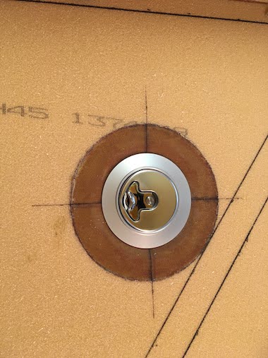
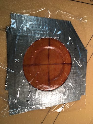 I recessed the foam in a couple of steps to accommodate the fuel cap recepticle and layed up 2 plies of BID. Used some plastic wrap to hold down the BID in the recesses.
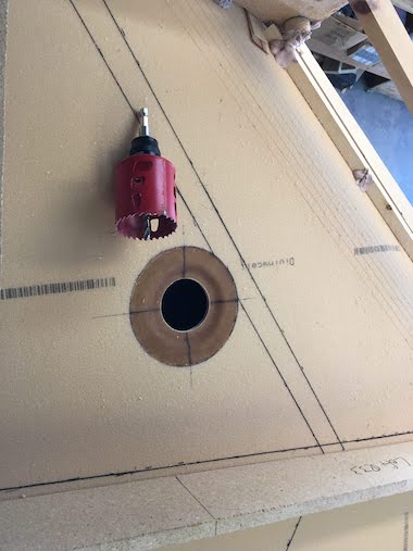 Then the fun part, cutting out the hole. I got a big 2" hole saw and went at it, actually it went fairly easy. The 2" hole was a little large for the cap recepticle so I recessed the foam in the hole and filled it with flox and then glassed the circumference and trimmed flat after cure.
36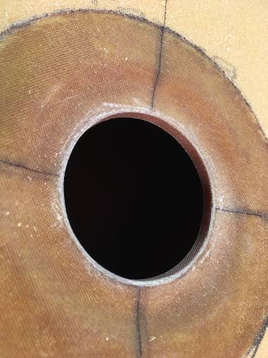
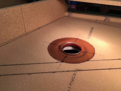
Here you can see the end result. The top skin glass will overlap the 1" outer perimeter of the glassed hole.
 The aft outboard compartment of the strake is empty space that is filled with pour foam. This is to ensure that fuel doesn't fill the cavity and cause the center of gravity (CG) to be too far aft. I made some cardboard walls so that the foam wouldn't spill over onto the T-hats and centerspar. That pour foam stuff is fun it really expands. After a couple of hours I trimmed it flat with a little hand saw.
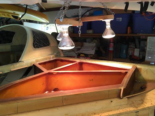
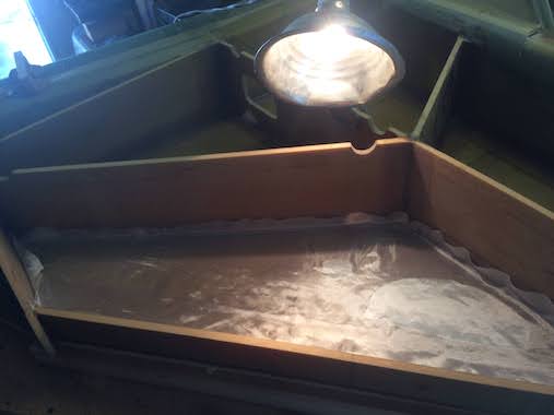
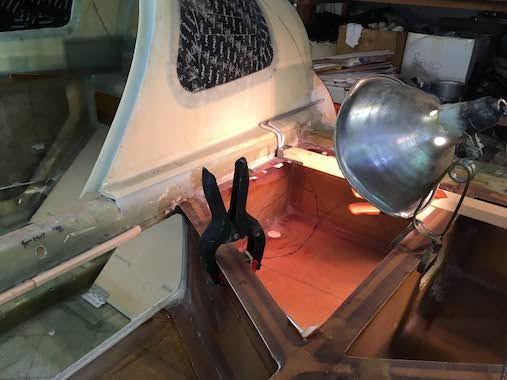
 I thought before putting the top skins on I would do a post cure, which is highly recommended especially by our epoxy guru Gary Hunter. The trick is not to get the surface temperature above 140 F. I made a little heat lamp chandelier but the heat was concentrated in the area just below the lamps.
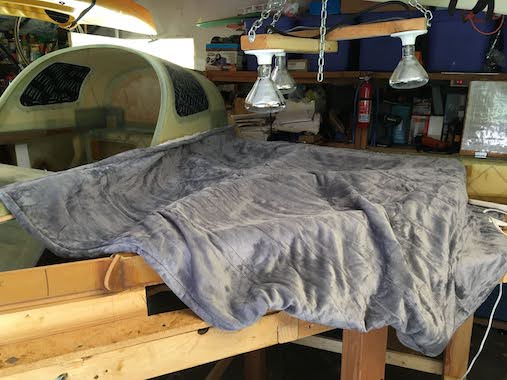
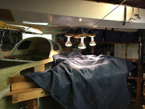 Gary Hunter recommended a heat blanket, so I got a $40 electric blanket from Amazon, that did help but didn't get the surfaces hot enough. I put a moving blanket over that and that did the trick. So I had the heat lamps, electric blanket and a moving blanket. I monitored the temps with a handheld temp sensor and indoor/outdoor temp monitor. I could get the temps between 125-130 F.
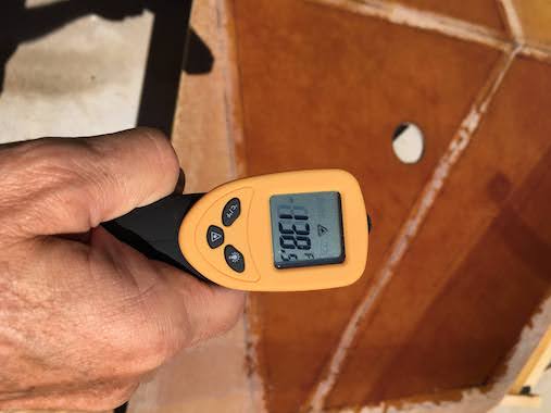 For post curing the inside surface (outside surface is still foam) of the top skins I could do that outside since it was over a 100F here in Southern California (SoCal). Gary Hunter said it's okay for unprotected fiberglass surfaces to be eposed to the sun for limited periods of time, just don't want to do it for serveral days, a few hours are fine and post curing only takes about 4 hours.
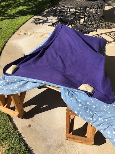
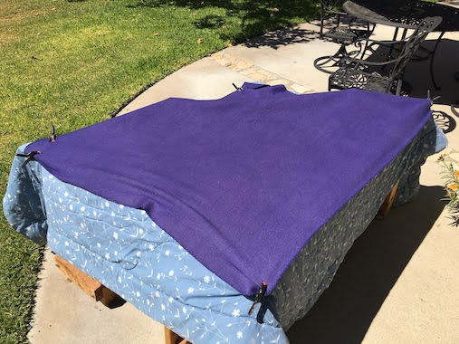 But with the SoCal heat the surface temperature quickly approached 140F within minutes so I layered blankets over the top skins and that insulated them a bit and kept the temperature around 130F.
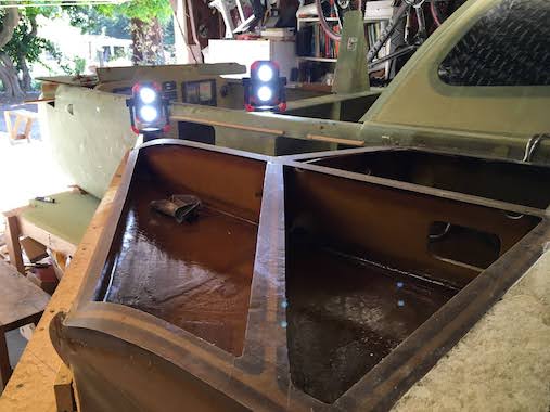
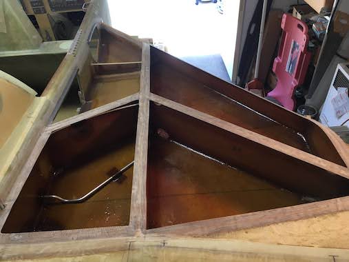
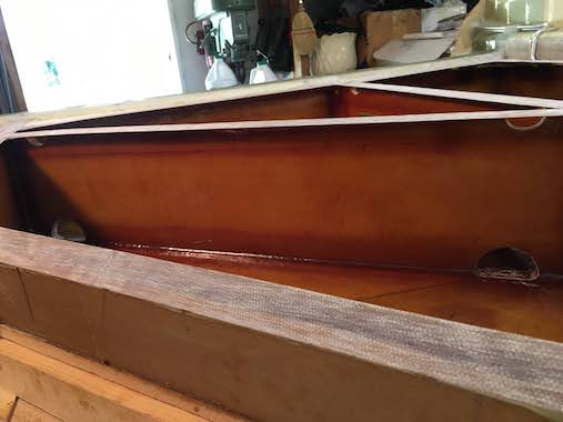 Just a last look at the strakes before floxing on the top skins.
 Everything is nice and shiny with a good coat of epoxy over the deck cloth.
 A close look at the vents.
 Everything is sanded and ready for floxing the top skins on.
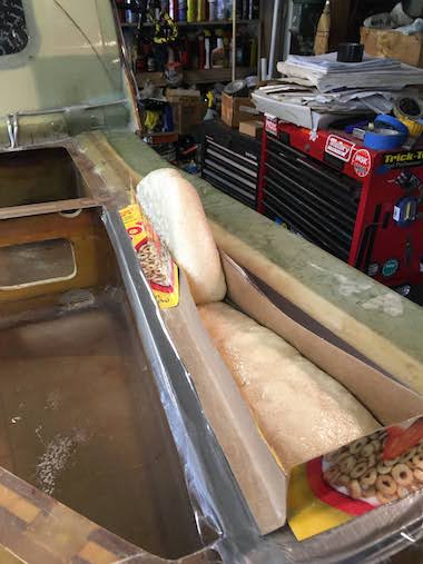
 The plans say to pile wet flox a half inch high over all the ribs and baffles where the skin will make contact. I think I managed that. Here's the right strake.
 Here's the left strake.
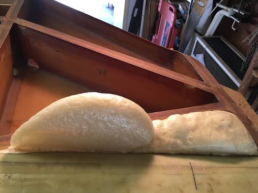
 More wet flox and the foam filler gets painted with epoxy.
 Here you can see the top skin weighted down for a good squeeze out of the flox. One thing to check is that the quick drain threaded holes don't get plugged up with flox that's squeezed out. One hole did have some cured flox cover the hole so it wasn't possible to thread the quick drain valve all the way in. With a hammer and punch I could break the small piece of flox away and vacuum it out. On the second strake I cleared away the flox while it was still wet with a Q-tip wetted with rubbing alcohol.
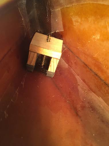
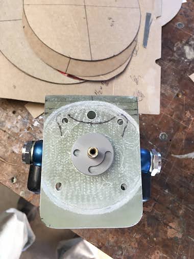
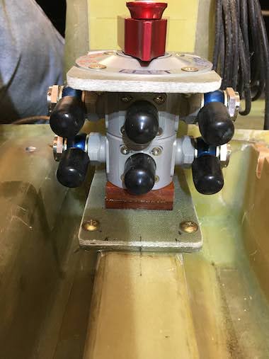
 I decided to make a bracket for mounting the fuel selector valve. I searched all the other builder's websites trying to see how to do it but I couldn't really find anything. I wanted to mount the valve just aft of the roll trim lever on the heat duct. The challenge is making a bracket that gives you complete access to all the ports for wrenching on the fuel lines. I himmmed, hawwed and came up with so many ideas but there was always a problem so I decided to just make fiberglass "U" bracket and go from there. So I made a glass bracket from about 20 plies of BID, couldn't make it too thick or else the valve template wouldn't fit low enough for the selector handle to turn. Even though I thought the thickness was thin enough I still had to countersink the glass where the template sits so the handle had enough clearance to be turned.
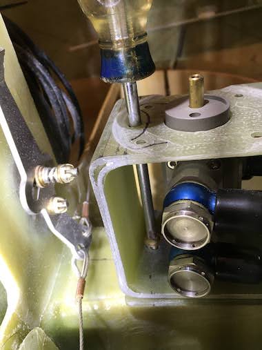
 I had to make the bracket a little taller than the valve so it could be angled inbetween the top and bottom bracket arms. I guessed on what that height should be and it came out just right. The other problem was how to keep the bracket from flexing down when pressing down on it when turning the handle or if you accidentally stepped on it. I thought of aluminum tubing supports with bolts going through but that would interfere with the fuel lines. So I decided on a phenolic block spacer between the valve and the bracket. So once the valve is angled in the bracket the space is screwed in place through the bottom of the bracket.
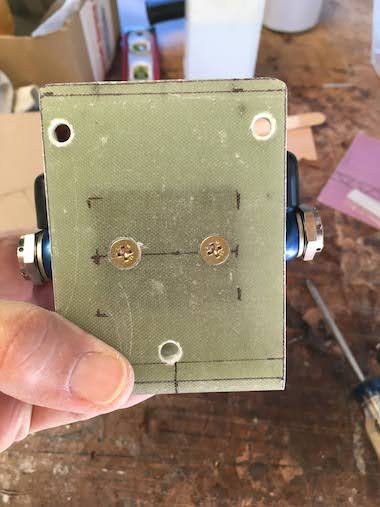
 I wanted the bracket to be removeable so it would be easier to detach fuel lines. So I made a mounting plate with nutplates riveted to it and floxed it to the heat duct. I wanted to make sure the screws would be accessible without interference with the fuel lines. The rear screw is accessible through a hole in the top of the bracket. I hope this will give me clearance from the fuel lines and allow access to the fuel lines.
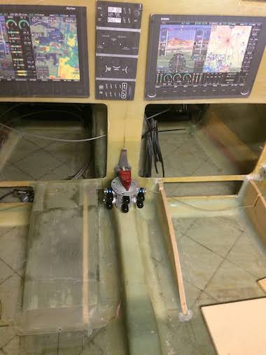
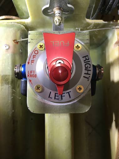 Here you can see the valve mounted. Typically a fuel selector valve is oriented so that the "Left" and "Right" positions are aligned with the left and right tanks respectively but that would require orienting the valve 45 degrees to the left which really makes a mess of attaching the fuel lines. Since the positions of the valve are so clearly marked and Right is pointing to the right tank and Left is typically the primary tank and pointing straight back to the engine where you want the fuel to go, it makes some sense, at least to me. It's also not possible to accidentally turn the valve to Off without pulling up the knob at the top of the handle. So if you accidentally run a tank dry and you're in a panic, just turn the handle right or left and hopefully there's fuel in the remaining tank.
 More pictures of the valve.
 And even some more.
 There was some Cozy group correspondence about the brake reservoirs from Matco being upgraded with a fitting and a seal into the bottom of the plastic reservoir so you wouldn't over torque the elbow fitting and crack the plastic reservoir. Since I bought my reservoirs so long ago I was thinking I needed to buy new ones but Matco had a kit for $40 to upgrade the old reservoirs which are the same as the new ones except for this added fitting and seal. I guess I should put this in the brake section.
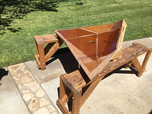
 One of the last pieces to the strakes is this diagonal end rib which gets floxed to the top and bottom skin and glassed to the small section of exposed center spar at the aft end and nose of rib R57 at the forward end.
 Here you can see them floxed and glassed in place.
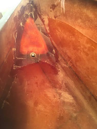
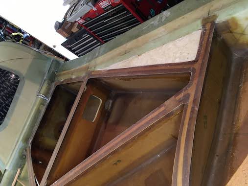
 So the only thing left to do before flipping the fuselage is to install the fuel feed line. It penetrates the fuselage side below the bottom strake skin. This seems a bit strange since it's below the actual tank but later you make a little sump below the strake that encloses the fuel feed line and the big hole in the bottom of the strake skin to ensure fuel is available regardless of the fuselage pitch or roll angle.
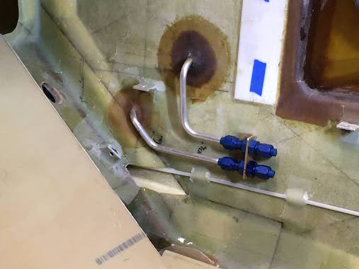
 Here is the right side. The top line is the fuel return line and the bottom line is the fuel feed line and below that is a plastic conduit for the rudder cables.
 I installed the fuel sight gauges, this didn't quite go without issue. I originally floxed the white acrylic sight gauge baseplates to the fuselage walls years ago. Before bonding on the top strake skins I countersunk (1/4") the holes for the sight gauges on the tank side and filled with flox using EZ-Poxy to ensure that the holes through the fuselage side that would be exposed to fuel would have the more fuel resistant EZ-Poxy. I floxed the clear bubble on the white acrylic back plate and noticed there were very fine circular crazed crack lines around the holes, I think countersinking overheated the acrylic which caused these cracks. I emailed Vance Atkinson, maker of the sight gauges, about the cracks, he hadn't heard of that issue before and didn't really think it a problem but offered some suggestions. Ultimately what I wanted to do was to take the sight gauges off and layup a couple plies of BID with EZ-Poxy over the area and flox on new sight gauges but thought it would be a pain to get the olds ones off. I was thinking having to Fein sand through the flox which is difficult while at the same time not damaging the fuselage wall and then more hand sanding. I told Vance what I wanted to do and he said no problem getting the old ones off especially since I hadn't done the BID tapes around the edges. Just take a chisel to flox line where the bubble is attached and give it a whack with a hammer and it should just pop off, then do the same for the acrylic base plate, I had it all off in 10 minutes. So I ordered a new set of sight gauges this time with an aluminum base plate so it is also resistant to automotive fuel with alcohol additives. The only tricky part was drilling the holes in the aluminum base plate to line up perfectly with the holes through the fuselage side walls. I made a cardboard template of the fuselage wall hole locations and marked the aluminum backplate and drilled the holes and they lined up perfectly. Now Vance provides eyelets with the sight gauge kits. They are super glued (Cyanoacrylate Adhesive) in the backplate holes which helps ensure you don't get flox in the holes. It turns out a coat hanger wire fits perfectly in the eyelets so when I floxed the backplates on I used some 4" lengths of coat hanger wire to align the back plates with the holes in the fuselage wall. It also ensures that the holes are cleared out of any epoxy. I used some duct tape to keep the backplate from sliding down and let it cure. I then floxed the clear bubble on the aluminum backplate and let it cure. Finally I taped the edges with 2 plies of BID.
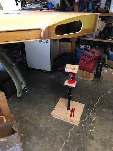
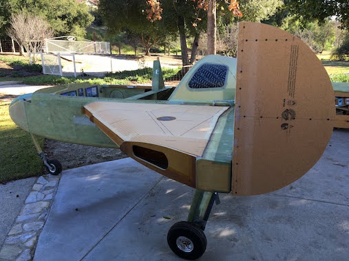
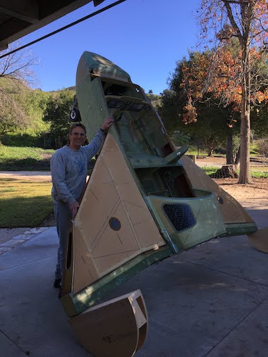
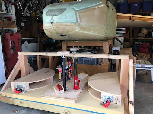 At this point the plans say to turn the fuselage over and glass the bottom of the strakes, easier said than done. Builders have done it different ways but the most common way is to build half circle "clamshells" that bolt on to the ends of the center spar using the wing attach holes. I wasn't sure how big to make them, just so that the turtleback clears the ground when upside down. Bernie Siu was the only builder that mentioned the radius of the clamshells being 14", somehow mine ended up 15" either way it offers plenty of clearance for the turtleback. Pretty straight forward construction using 2x4's and particle board from the strake tables. I did add a little feature to mine with a removable caster wheel at the bottom so I could roll the fuselage. I modified my low rolling sled with a saw horse to support the front end of the fuselage. I also needed to be able to lift the fuselage off the cart it's been sitting on. Before I would do it with chain blocks but now with the strakes attached there's no way to loop straps around the centerspar. I bought a set of 48" RV stabilizer jacks, only $65 on Amazon. The only problem is that the base is only 5" in diameter so I sandwiched the base between particle board, 18" sqaure. I countersunk a 5" circle the thickness of the base in one of the squares and then screwed the squares to together with the base sandwiched in-between. I screwed a 2x4 block in the metal bracket on the top of the jack stand and countersunk the pattern of the bottle jack base on the top of the wood block. It always seems nothing wants to stay in place when you're jacking things up, a lot of automotive maintenance experience. I also made a wood block with a plywood piece screwed to it to go in between the bottle jack and the bottom of the center spar, this spreads the load and ensures the bottle jack is lifting in the strongest part of the centerspar. I countersunk a circle the size of the bottle jack rod in the bottom of the block to make sure it lifts in the correct spot.
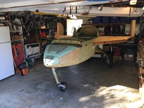 So here it is the first time the fuselage is sitting on it's own gear. Most builders have 4 or 5 people to help them flip the fuselage but I was hoping Lynn and I could do it ourselves since we'll probably need to do this several times, to flip it back upright to glass the top of the strakes and flip it over again for finishing.
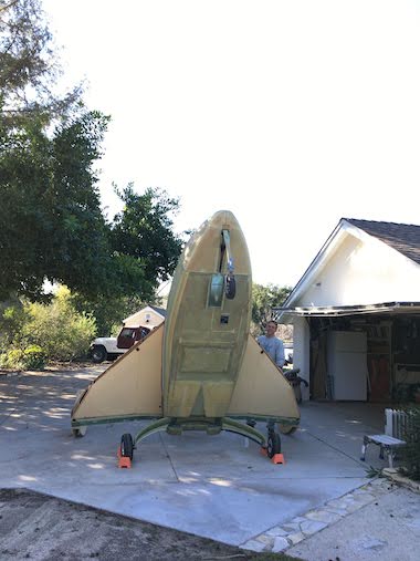
 It was actually pretty easy to get it to the apply named "Space Shuttle Launch" attitude. But getting it to go over center we just didn't have the muscle to do it. I could have possibly pushed from the underside to get it over but was concerned that it might fall over quickly and there would be no way Lynn could catch it.
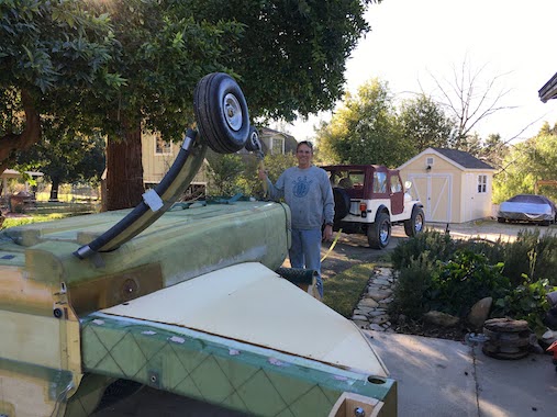
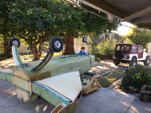 So we put a strap around the nose of the fuselage at the canard attach bulkhead so it wouldn't slip off and hooked a long strap to it and Lynn's Jeep. Lynn pulled the fuselage with her Jeep to the tipping point with me ready to keep it from falling over. Once at the tipping point Lynn set the brake on the Jeep, got out and helped me lower the front of fuselage down unto the rolling saw horse. It actually came down quite gently, at one point I told Lynn to stop holding up the fuselage and she said she wasn't. I think the large radius of the clamshells helped make lowering the fuselage more manageable, could also be that the wing attach points cause the clamshells to be toe'd in a bit offering some resistance. Whatever it was I think we'll do it the same way next time.
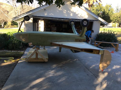
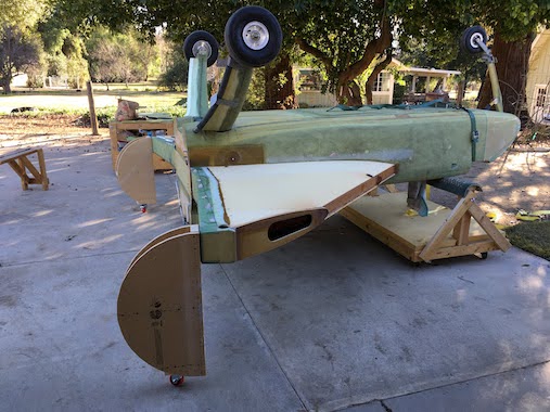 Here I attached the caster wheels to the bottom of the clamshells so we could roll the fuselage back in the garage.
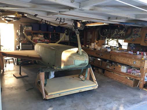 All safe and sound in the garage upside down, just need to retract the nose gear. Used the RV jack stands to take a bit of the load off the clamshells.
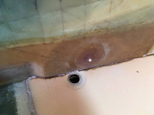
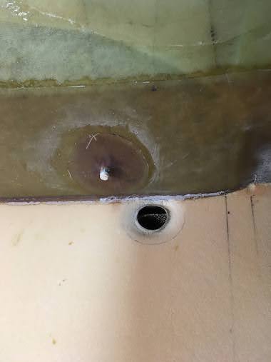 Started prepping the bottom strake foam for glassing. I ground down all the flox along the fuselage sides and centerspar. Around the 1-1/4" fuel outlet hole I shaped the foam into a bevel and ground down to the glass of the inner skin to make a flox corner there. Before grinding and sanding I stuffed strips of duct tape inside out into the hole to capture foam and grinding dust. Also rounded all the strake leading edges and outboard diagonal (OD) rib so the glass would lay over the edge easily. Also along the leading edge and OD foam I sanded a 1/32" depression 1" wide to accommodate the glass layups of the foam leading edge and strake to wing fairing foam block.
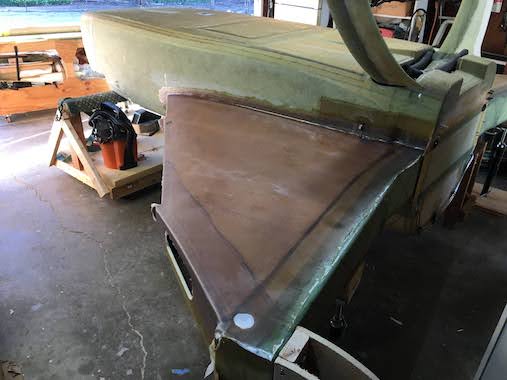
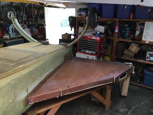 Here is the right strake bottom glassed. It consists of three layups, one ply of UNI parallel to the leading edge, a second ply of UNI parallel with the fuselage and a small third ply of UNI 5" wide along the OD rib. The UNI plies overlap the centerspar by 4", the fuselage side by at least 1", the leading edge completely and half way down the OD rib. We peel plied the entire layup. It took us 4-1/2 hours to do the layup.
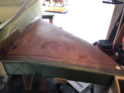
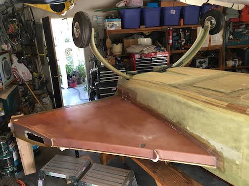 Here is the left side glassed as well.
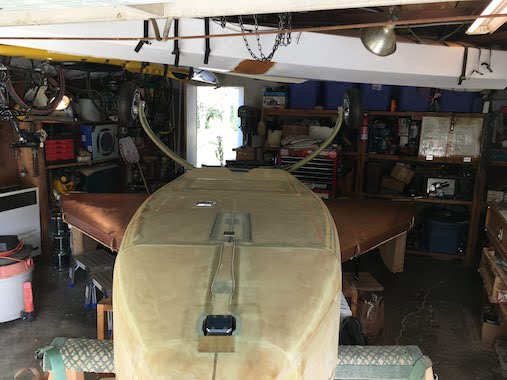 Both sides glassed, Yippee!
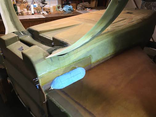
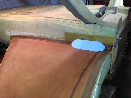 Started shaping some foam to make the strake sumps.
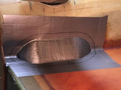
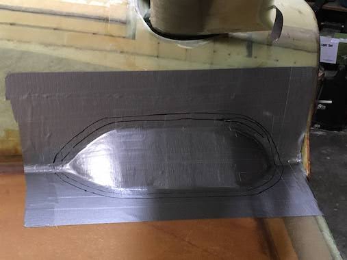 I duct taped the sump plugs in place.
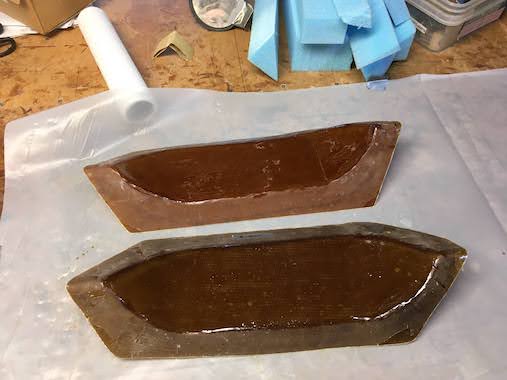
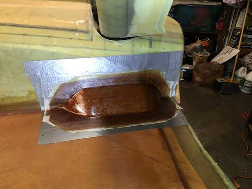 Then each sump gets 4 plies of BID. The second picture is the inside of the sumps with a heavy coat of epoxy and a ply of deck cloth to seal them.
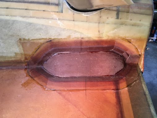
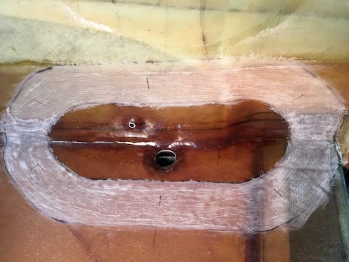 Here is the right strake and fuselage side prepped to flox and tape the sump in place. The area that will be exposed to fuel also got a heavy coat of epoxy and deck cloth. The picture also serves as evidence that I did indeed remove the plug from the fuel line and opened the 1-1/4" hole before floxing/taping the sump on.
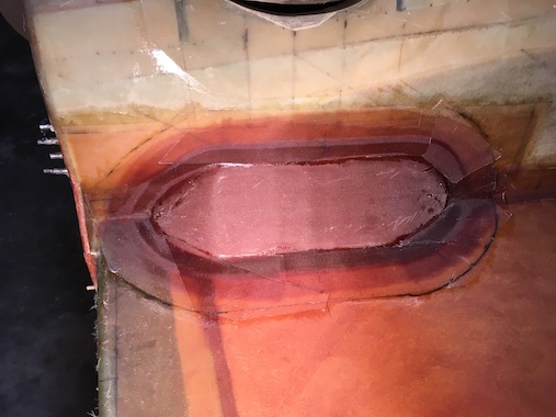
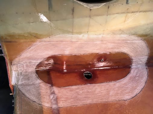 Here is the left strake sump. The sumps will eventually get covered with a fairing to smooth out the airflow.
Now I get to flip the fuselage right side up and glass the top of the strakes. Oh Boy! Need to wait for the rain to stop though, quite the rainy season for SoCal this year.
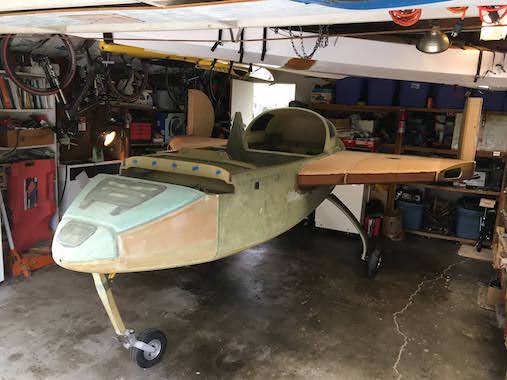
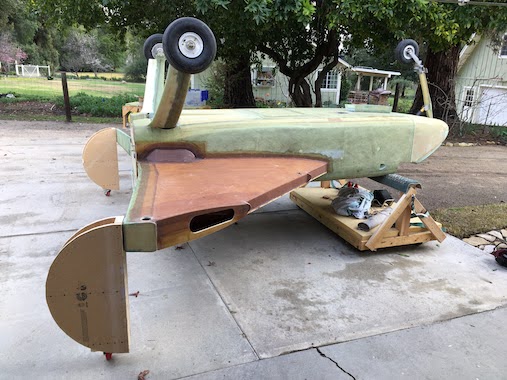 The bottom of the strakes are done so flipped the plane over again. A little easier flipping it right side up, didn't need Lynn's Jeep.
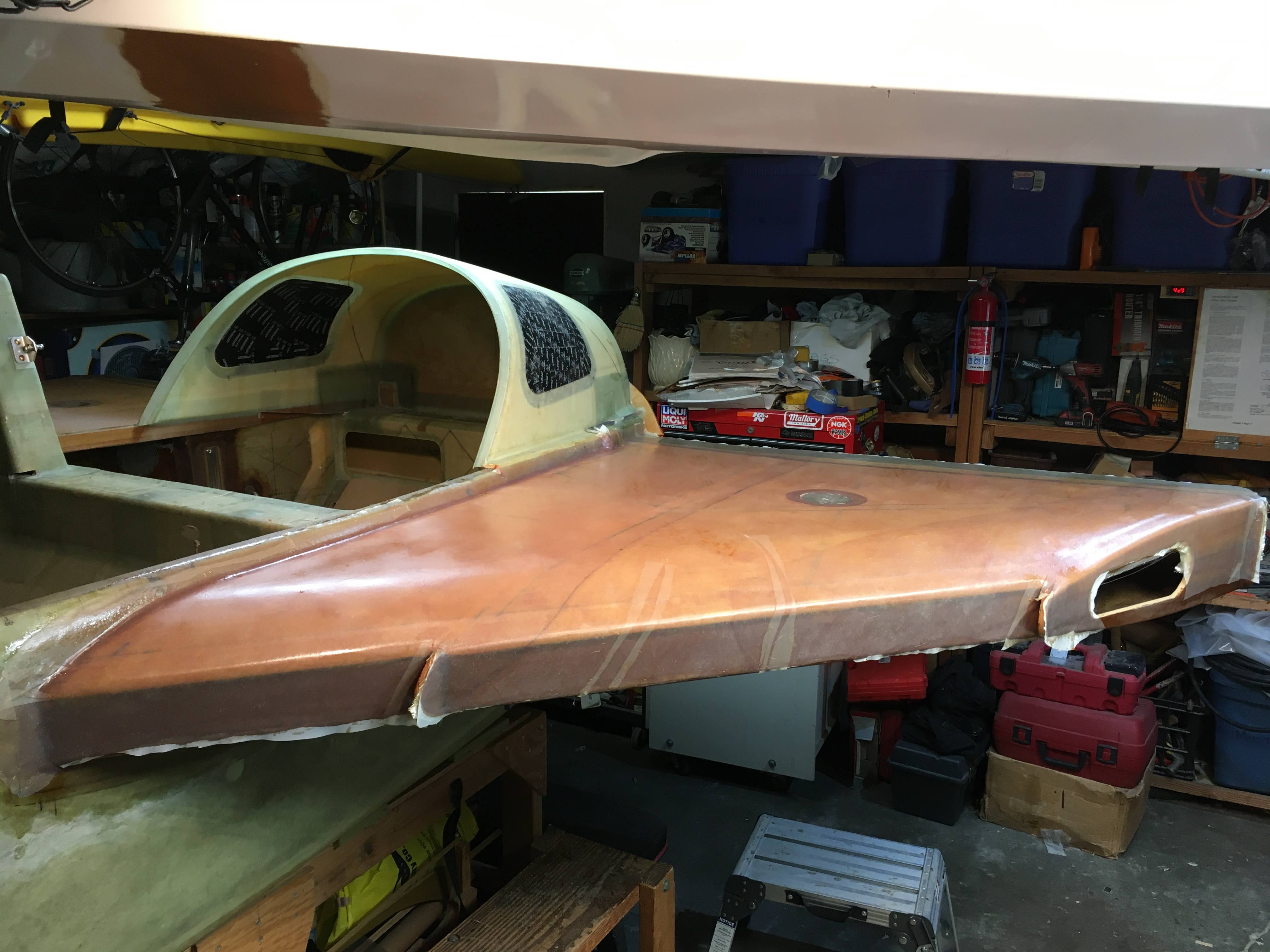
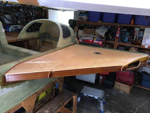 We finished glassing the tops of the strakes which was the same as the bottom with an additional ply of UNI at a 45 degree angle with the fuselage side sweeping forward so that it would be at 90 degrees with the first ply which is parallel to the strake leading edge. This additional ply goes just a little beyond the long inboard rib to give extra strength for getting in and out of the airplane and fueling the tanks. The first picture is the foam micro'd and flox fillet along the fuselage and blending the foam to the center spar, that alone took an hour and a half. The second picture is the completed top skin with peel ply, the whole layup took 5-1/2 hours.
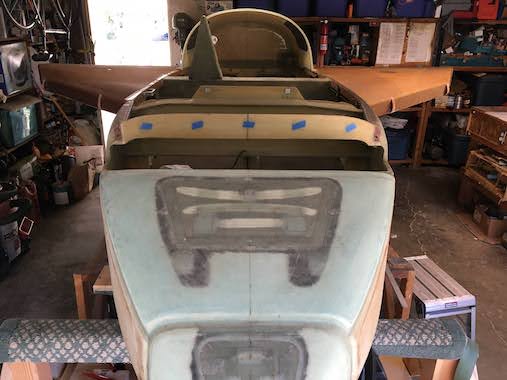
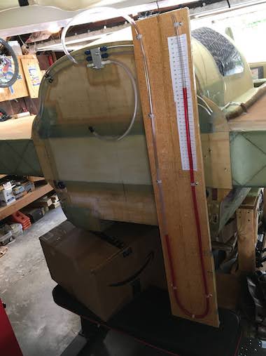 So now that the tanks are fully enclosed it's time to pressure check them for leaks. I made a manometer following the instructions from I Fly EZ, thank you Waiter (I don't know his real name). Waiter has a pdf file of the plans and scale. It's good to use his scale because the inches are actually 1/2 inches. When measuring inches of water you have to add the amount one side of the manometer goes down to the amount the other side goes up or just halve the amount the one side goes up. I would not have realized this and over-pressurized the tanks by double. The manometer also needs to be vertical so I hung it from the rafters with some tie wire. The plans have you use an altimeter by setting it to 1500 feet and then pressurizing the tank so that it indicates 0 feet and monitor that for 24 hours for any drops, fluctuations due to temperature are okay. Altimeters have become expensive and since I'll have a glass display I have no need for an old analog one. So the difference in pressure from sea level to 1500 feet is about 0.76 psi and converting that to inches of water is about 21.0". That makes the manometer super sensitive to any changes in pressure which was evident by pressure changes due to temperature. Since both tank vent lines come to a common manifold at the top of the turtleback firewall I decided to test both tanks simultaneously and if there were leaks I'd troubleshoot them individually. Initially there were leaks but primarily at the vent line AN fittings, one was absolutely stubborn, but after completely loosening it and putting it back together it was air tight. Oh, you use a soapy water solution to find the leaks, the leaking air will blow bubbles. I put AN cap fittings on the fuel feed and return lines inside the fuselage they also leaked a bit but just needed a little tightening.
 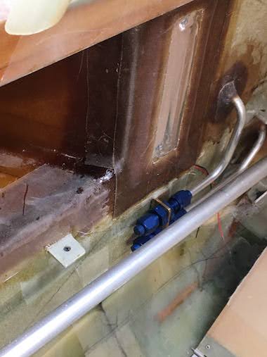 I forgot about the tank quick drain plugs at the leading edge and they were also leaking because they were only hand tight, I put a little teflon tape on them (which has been removed because you don't want to use teflon tape on pipe threads on a fuel system because they can flake off and get into the fuel system) the actual quick drain valve will have pipe thread sealant.
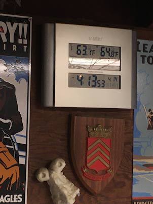
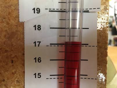 So you blow into the tanks and pressurize them to 21" of water, I could get up to 21" but by the time I plugged the tube it would drop to 17" even after several attempts. You don't want to go much higher than 21" or you could blow the top skins off the strakes. So I started off at 17" at about 4 pm and 65F. It was good I did because as you'll see the next day the temperature really warmed up and the pressure went up to 22".
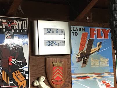
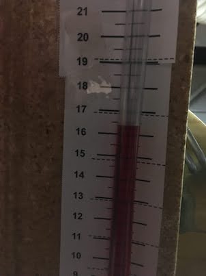 So as the temperature dropped so did the pressure. Here at about 10:30pm the temperature dropped about 4 degrees and the manometer dropped about a 1/2".
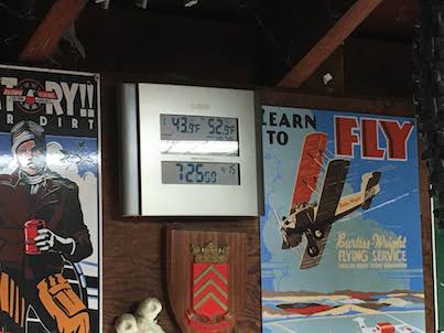
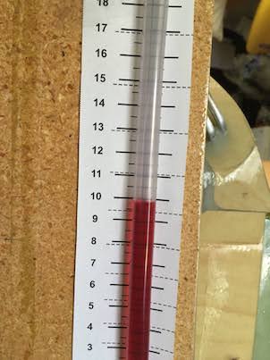 The next morning at 7:30am the temperature had dropped about 9 degrees and the manometer had dropped about 6-1/2 inches. It was a little concerning that the manometer dropped so much but the overnight temperature dropped to 35F so it got pretty cold and I think there was a lag for the tank to warm back up.
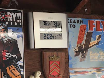
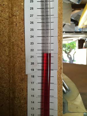 During the day as the tank warmed up the manometer continued to rise, it was a much warmer day. By 2:00pm the manometer was at 21-1/2".
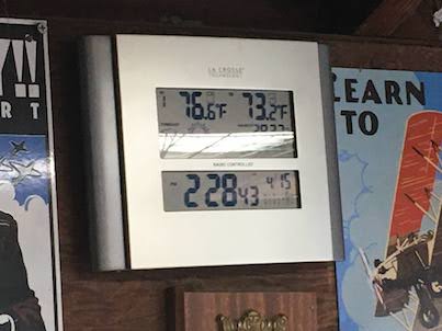
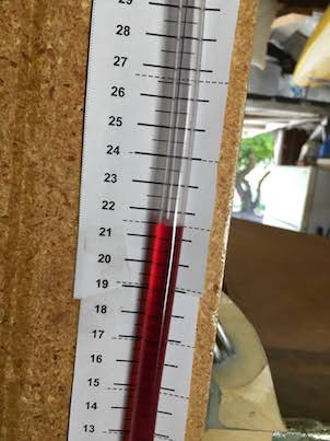 I was watching the manometer closely because it was climbing steadily, within a 1/2 hour it was nearly at 22".
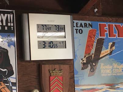
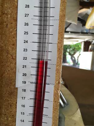 The pressure was going beyond 22" so I released some pressure by loosening one of the quick drain plugs slightly while Lynn watched the manometer drop back to 21".
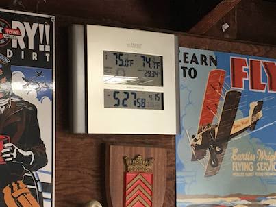
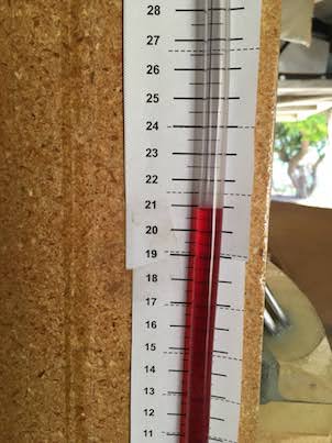 So at 5:30pm more than 24 hours from starting the pressurization test the manometer was holding at 21". I though I'd let it go longer to see how the pressure dropped as the evening temperature dropped.
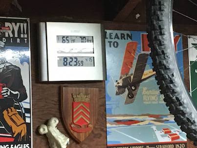
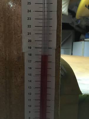 At 8:30pm the temperature had cooled about 4 degrees and the manometer did drop about 3" to 18". So it seems that temperature really influences the pressure in the tanks and the manometer is very sensitive to any pressure changes. Overall I'm convinced the tanks are air tight, if there were a leak it would have leaked down completely to zero over the 24 hour period. YAY! No Leaks!
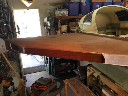
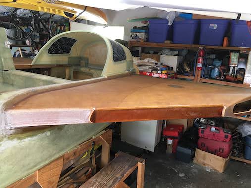 The plans have you paint on more epoxy on the tank leading edge bulkheads, since you won't have access to this area once the actual leading edges are glassed on. I can't imagine this area ever leaking since there are already 4 plies of UNI there. I put the deck cloth with a thick layer of epoxy on anyway. I didn't put it on the inboard section since this area is a baggage compartment and there is no fuel.
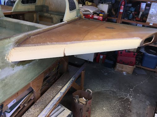
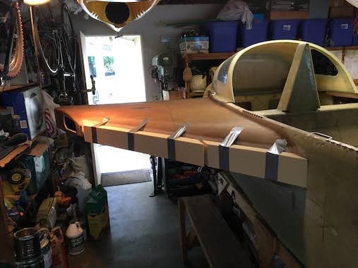
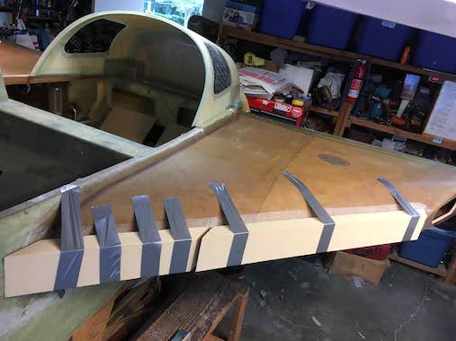 Time to make the strake leading edges. Per the plans I 5 minute epoxied some urethane foam, to the leading edge bulkheads. Again the foam is urethane because it is fuel resistant but it is so soft that if you look at it wrong it will dent. Somehow I still had 4 sheets of 2" thick foam and cut one of them into 4" wide strips and angled the ends to fit within the nose ribs and the fuselage. I first started to whittle the blocks with a small hand saw but that was a mistake because it was too easy to take too much off. So I put on a new foam strip and sanded with a 6' long aluminum "T" bar 3" wide with 36 grit sand paper glued to it. I had this sanding bar from when I shaped the wing foam. This made a lot of foam dust but I just took my time sanding using the nose ribs as guides and eventually the leading edge took shape.
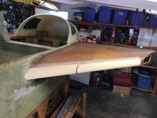
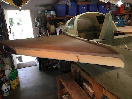 I think it took about 25 minutes of sanding, each side, to get to a fairly good shape.
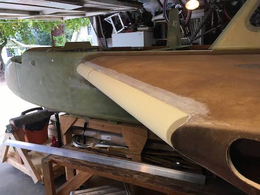
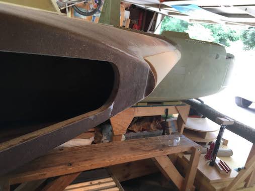 Sighting down the outboard nose rib you can see that the shape closely matches the nose rib. The plans don't want you to change the leading edge profile. I also used some 150 grit sandpaper to smooth out any ridges from the long sanding "T" bar.
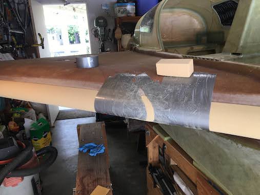
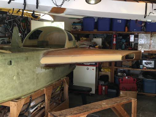 The only problem was how to fill the gaps at the nose ribs. I was first thinking to fill with micro but decided it would be too much to fill. So I shaped some foam to match the nose rib contour and 5 minute epoxied it in place. I duct taped on either side of the foam and sanded the filler foam block with another piece of foam until the contour matched. It would have been better to put the filler nose rib foam block in place with the long foam blocks but I couldn't visualize how it was all going to come together.
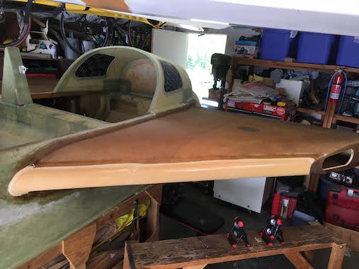
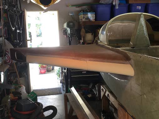 Here is the right side with the final foam leading edge contour and the left side micro'd ready for the 2 pies of UNI. I made the micro very thin and brushed it on so that I wouldn't make ridges in the foam with a squeegee. Used thick miro to fill the gap between the foam and the leading edge bulkhead and at the fillet with the fuselage.
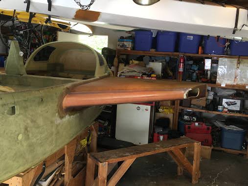
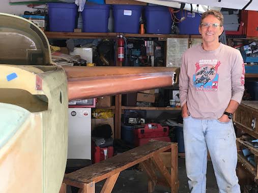 The leading edge gets two plies of UNI at 45 degrees. Lynn insisted of a picture with me. The leading edge layup took 2-1/2 hours for one side.
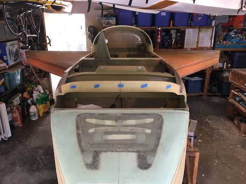
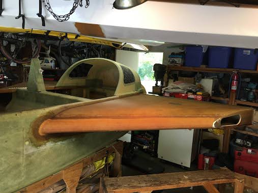 Now the strake looks a little more airfoilish. Both leading edges glassed. Yay!
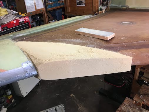
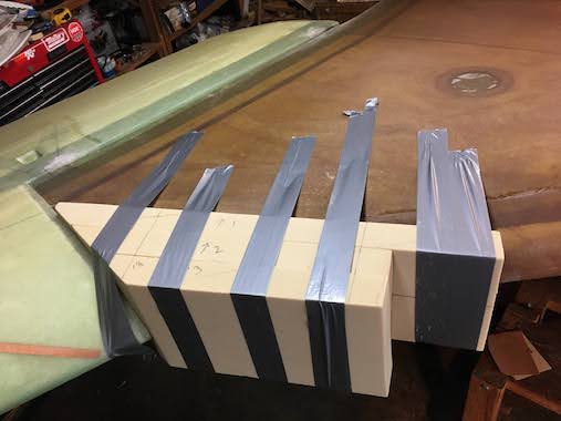 Needed to make the transition blocks betweem the strake and the wing. So we had to bolt the wing on, we started with the right side. More pictures below of the wings bolted on when removing the right and bolting on the left. I 5 minute epoxied some urethane foam blocks to the strake and started making a lot of foam dust, good to have the shop vac nearby.
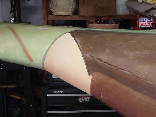
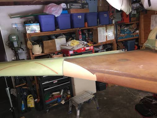 Looks pretty shapely, hopefully it will look good when glassed and painted.
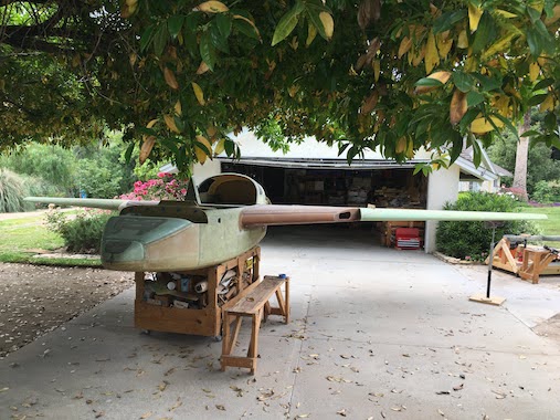
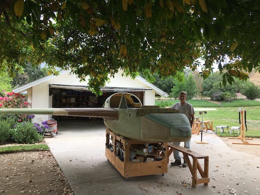 Here are some pictures with the wings bolted on. The thing is with only one wing bolted on the fuselage wants to roll off the cart so those RV stands come in handy to prop up the wing. I made some wing stands out of 2x4's a while back and they work but are really heavy and cumbersome need to find out how others have made their wing stands for something more efficient.
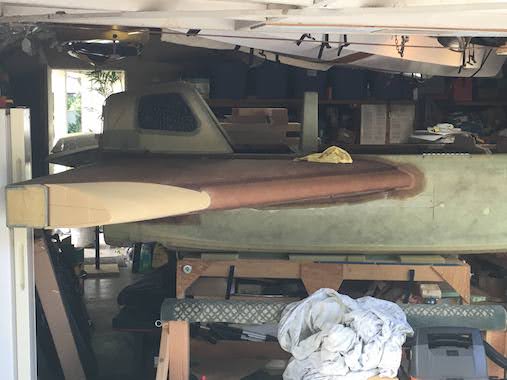
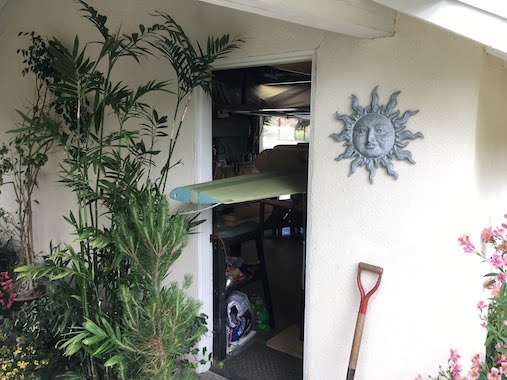 It was a little difficult to get the plane to fit in the garage with the left wing bolted on but managed by sticking the wing tip out the people door.
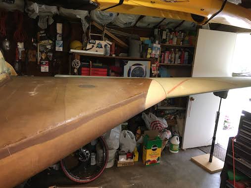
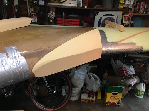 Sames steps as before, more sanding and shaping and voila another shapely transition block done.
At this point we went to the Canards West Flyin, a good 6 hour drive for us to Northern CA but we love road trips and especially this part of the state. This is gold rush country and many of the towns have that old west feel. Columbia State Park within walking distance of the airport is an old west town with a hotel that you can stay in many of the canard pilots/builders who fly in stay there. Here are some pictures and videos of the flyin.
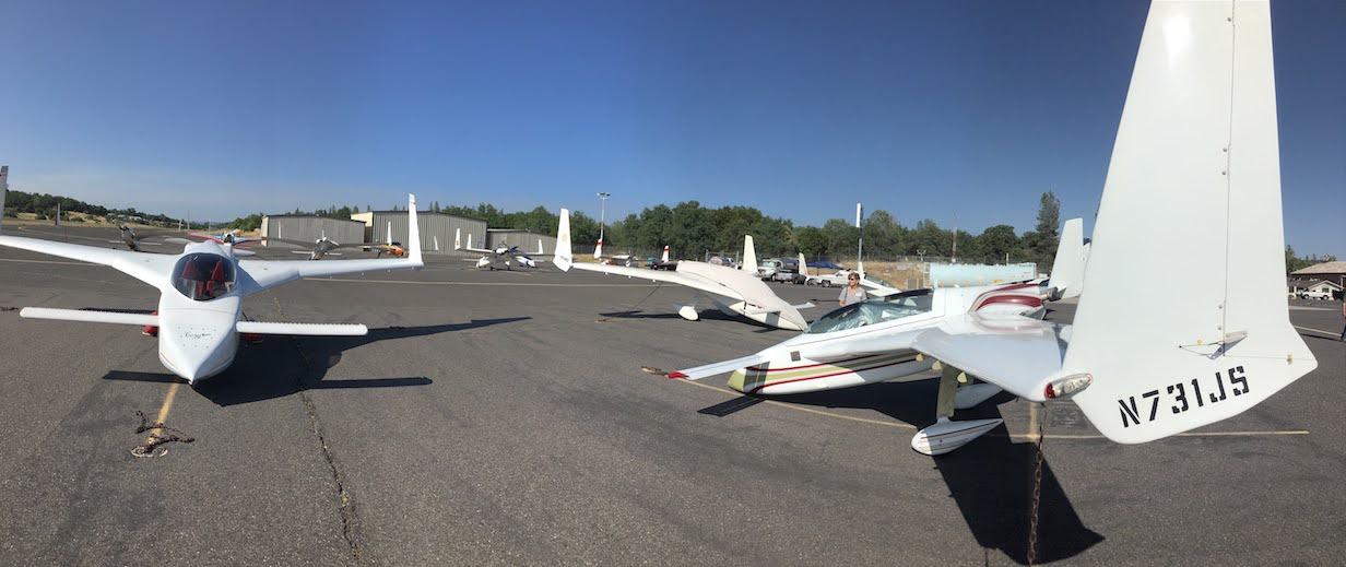
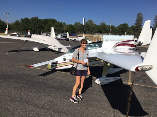
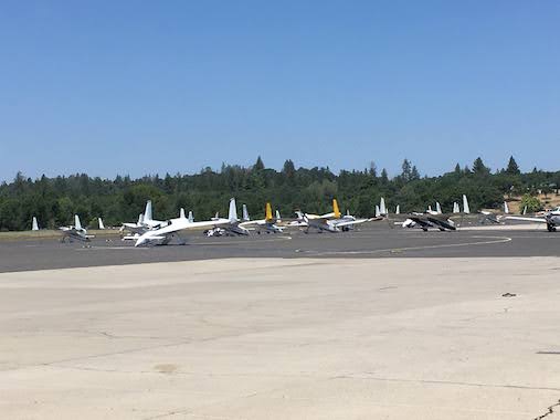
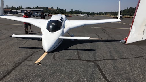
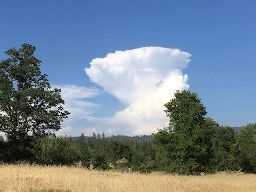
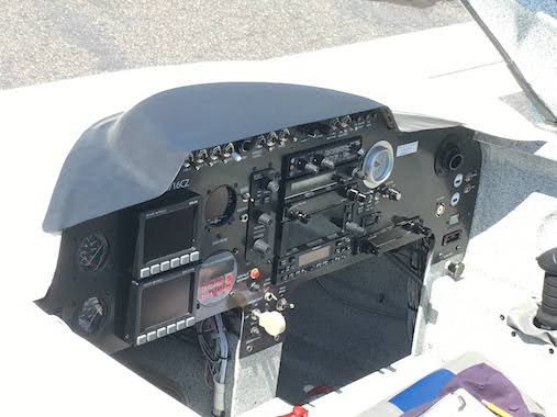
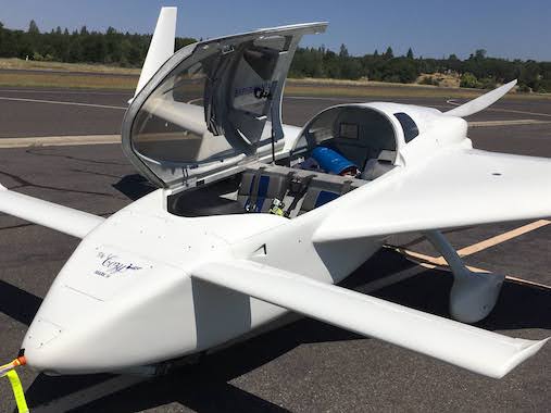
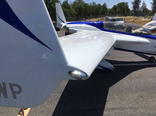
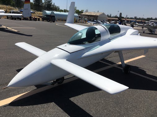
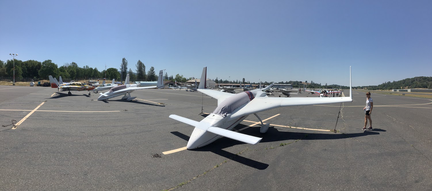
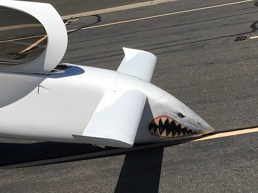
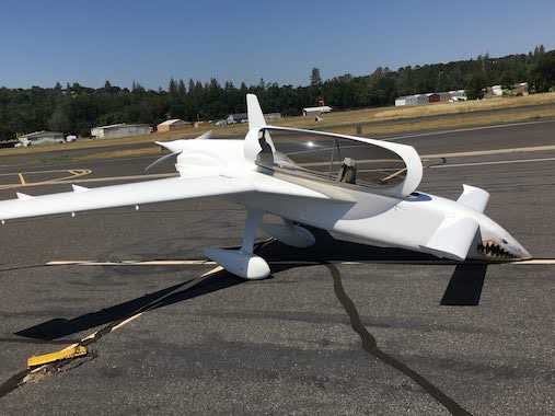
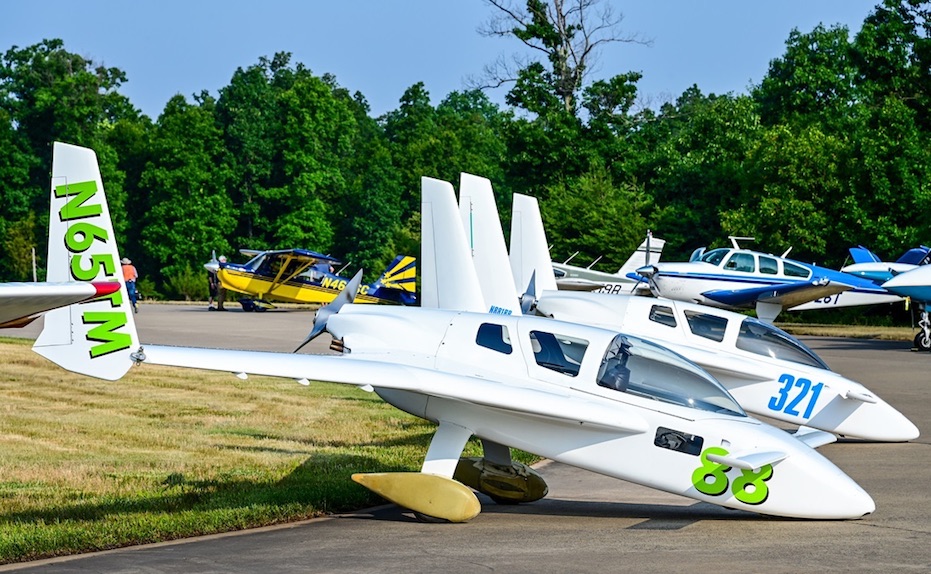 This is a picture of Russ Meyerriecks and Bob Bittner's Cozy's at the Udvar-Hazy Smithsonian Air Museum near Dulles Airport. They were invited to display their airplanes at a special General Aviation Day. Cool picture.
So back to work glassing the strake transition blocks with two plies UNI crossing each other.
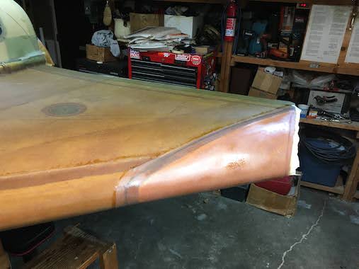
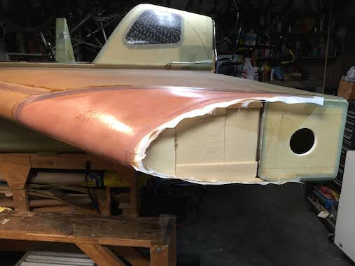
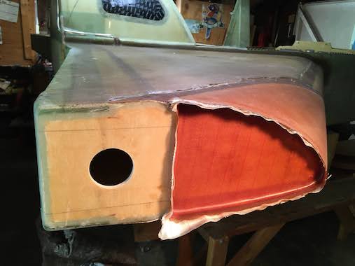
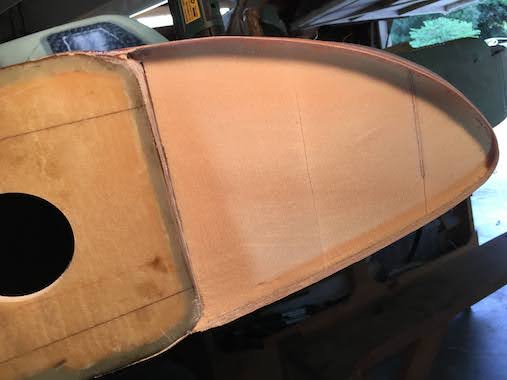 I recessed the foam in the end of the transition block and layed up 2 plies of BID.
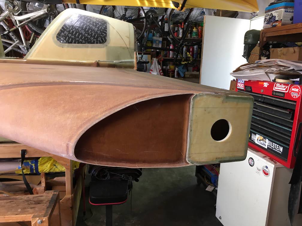
All the strake structure is done but to complete the chapter you need to complete the fuel line plumbing. As luck would have it Marc Zeitlin was installing the SDS electronic fuel injection/ignition system in his airplane to complement his newly rebuilt engine. He wanted to make fuel filter changes easier so was installing a filter at each strake with a fuel shutoff valve. I went with a Earls S/O Valve from Holley, picture is link (trying some new html code).
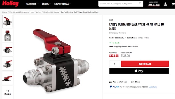
I decided to make a bracket to hold the fuel S/O valve.
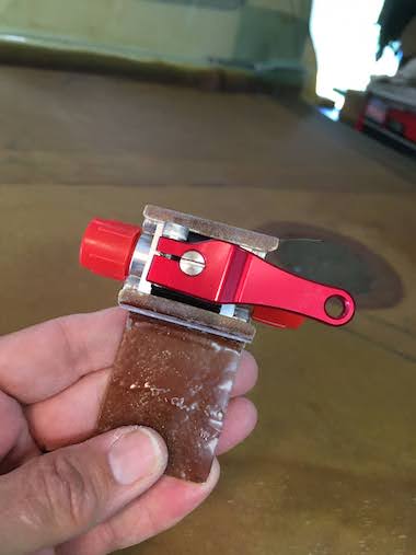
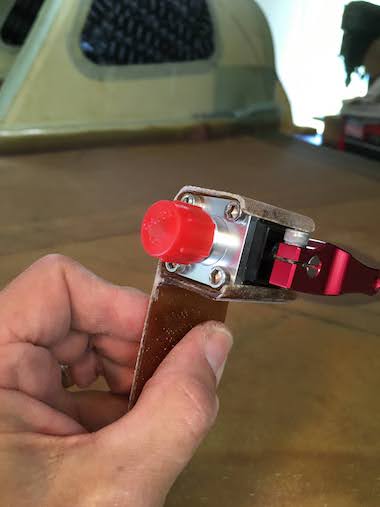
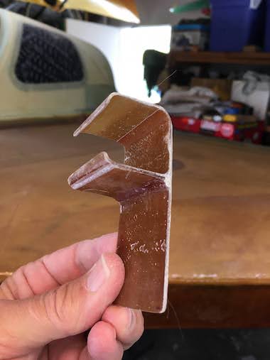
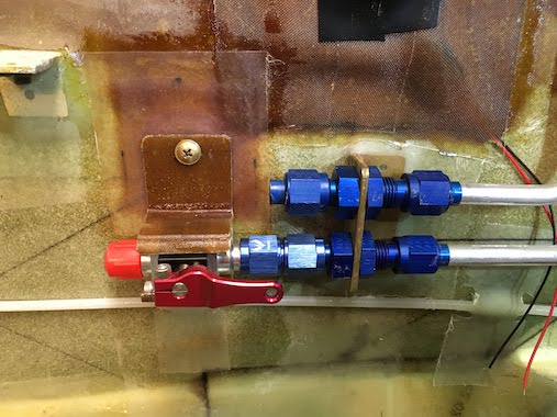
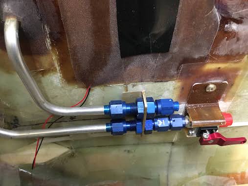 I embedded an 1/4" thick 1/2" square threaded piece of aluminum in the fuselage wall to screw the bracket to.
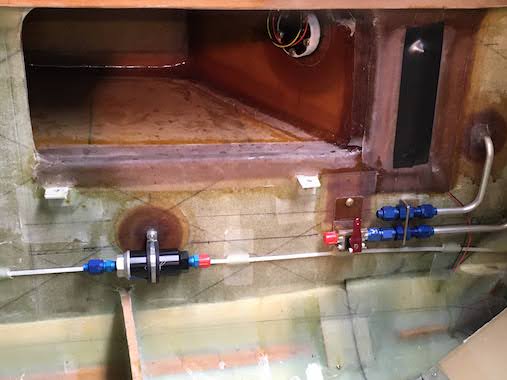
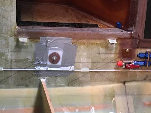 I floxed a "Click Bond" to the fuselage to mount the "Adel Clamp" holding the fuel filter. I had to come up with a way to hold the click bond in place while the flox cured. I used plastic from a gallon jug of distilled water, cut a circle with lines through the center, made a hole in the center to hold the stud of the click bond and duct taped it. This way I could mount the click bond exactly where I wanted it, worked great.
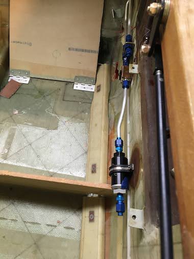
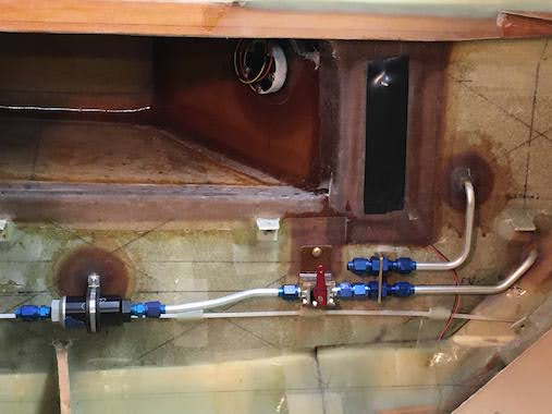 I bent the tubing down and out to join the shutoff valve to the fuel filter for both sides. Took some trigonometry to figure that out. I made the tube longer than it needed to be so I'd have room for the flaring and bending tools. Might regret that as there will be some fuel in the line when disconnecting to change the filter.
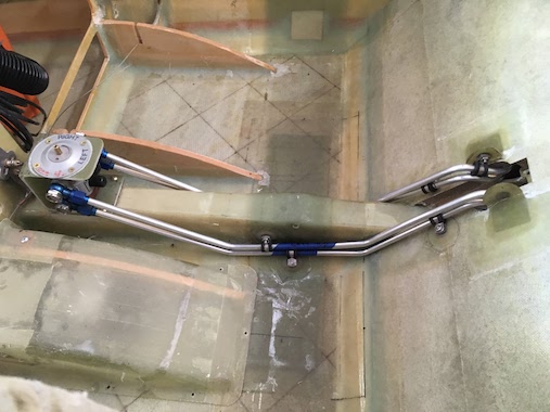
 Decided to plumb the fuel lines from the front to the back. The hard part was to make the two 90 degree bends to get the lines through the holes in the seat back support (the same holes that would be used to route the fuel lines for the plans seatback mounted valve) to run horizontally along the back of the seat back. After several tries got the tubes bent and floxed/glassed some click bonds for fuel line clamp attachments. 3/8" tubing needs to be supported every 16 inches.
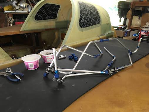
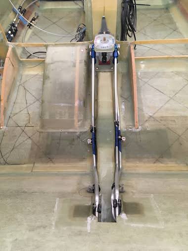 Another view of the front fuel lines routed through the seatback. Also the menagerie of fuel lines for the back seat area.
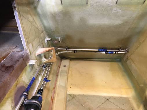
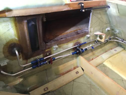 Here is the left side routing of the fuel lines. I used Goodridge 811 stainless braided fuel lines forward of the fuel filter to make changing the filter cartridge easier. If you use a braided fuel line be sure it is "Anti-Static", the fuel flowing through the line can create a static charge which can cause pin holes in the PTFE lining. I fabricated the hoses using the Pegasus instructions and Goodridge fittings and pressure tested them to 80 psi, which is overkill since these lines will only see gravity feed pressure from the strakes. The fuel pump pressure will be 40 psi so I thought the braided line should easily handle double that, it would only be if I didn't do a good job installing the fittings that it would leak, but no leaks, yay!
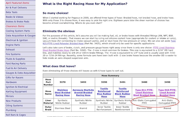
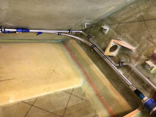
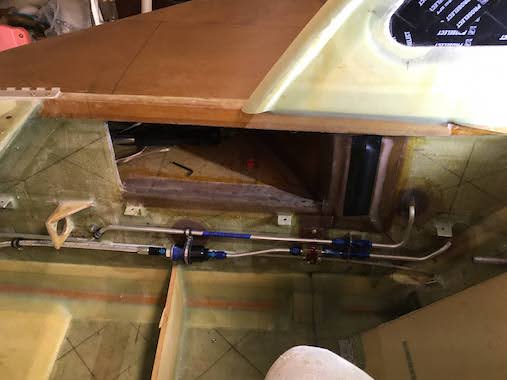 Here is the right side. Floxing/glassing all the click bonds especially on the seatback was a real pain having to fold your legs up into a pretzel to fit in the back seat area. I remember someone saying a long time ago not to put the rear seat bottom bulkhead supports in until the very end so working in the rear seat area would be much easier. Now I understand why.
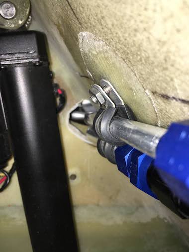
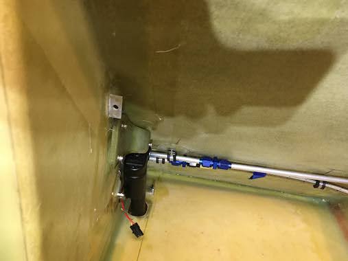
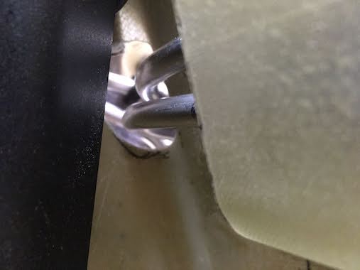 The challenge with the right side was to make sure that the speed brake actuator would not contact the fuel lines as it moves when deploying or retracting the speedbrake, but there was plenty of clearance. I did need to open the holes in the seatback brace a bit to provide adequate clearance. Now I need to make some covers to protect the fuel lines.
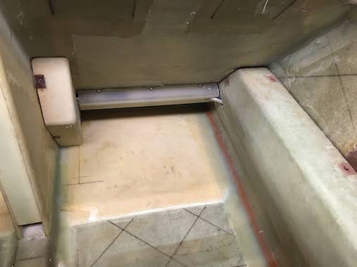
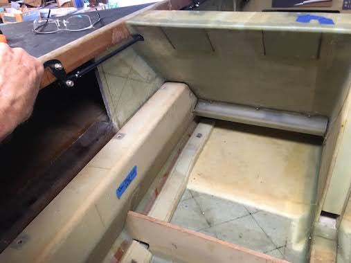 I made some covers from 3 plies of BID and embedded some 1/4" aluminum threaded slugs into the seat back to screw them to. The covers can also double as foot rests. It was a real pain to work back there under the seatback.
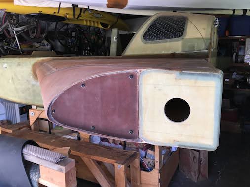
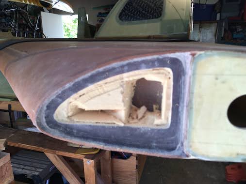 In one of the Cozy emails I heard Marc Zeitlin talk about how the empty space in the end of the strakes make for a great place to install a magnetometer since it's far from any metal objects which would interfere with the sensor. I had glassed over the end of the strake to wing fairing block with 2 plies of BID. So I needed to open that up and hog out the foam to create the space. Before I cut open the end I did two separate layups of 3 plies of BID, one to create a cover and another to create additional plies for a lip to attach the cover to. I made the bottom of the opening level with the longerons since the magnetometer needs to be level in both axes and parallel with the centerline within one degree.
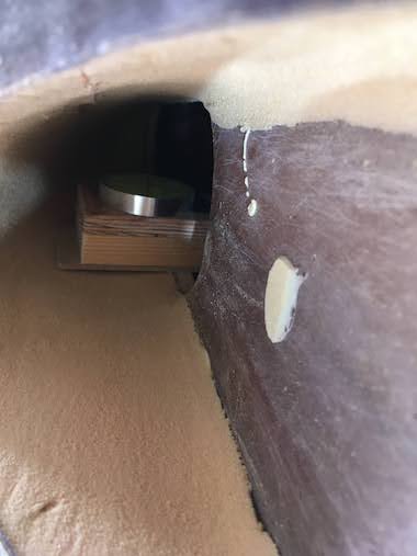
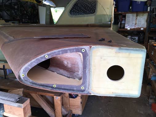 I made a slightly larger mock-up of the magnetometer to see how it would fit and realized that I needed to lower the bottom a bit. I was hoping I could shape the foam level with the bottom cutout and laterally as well but the urethane foam sands away so easily that, that didn't workout. I'll have to make a platform for the magnetometer to mount to and level that in the opening after glassing. I got a little 2" bubble balance that shows level horizontally.
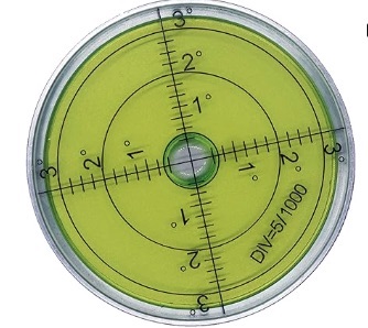
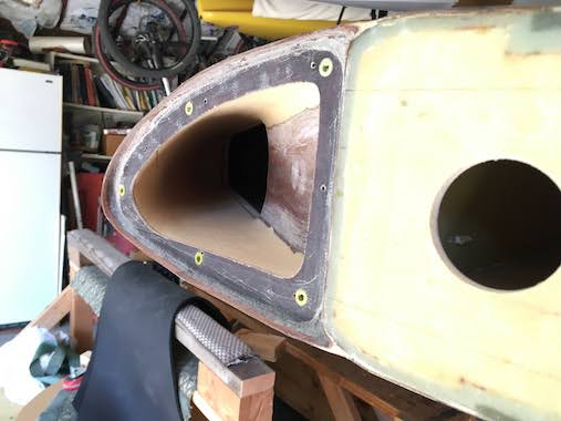
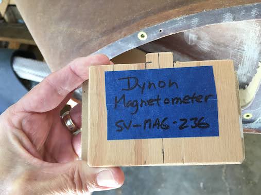 I decided to try rivnuts to mount the cover. Rivnuts are threaded inserts that are attached like a rivet by deforming the back side to keep it in place. I used flush, keyed, #8 rivnuts. The rivnuts are aluminum and you need to use brass screws so that there's no interference with the magnetometer heading. Nothing can be ferrous (magnetic) near the magnetometer. You need a special tool to insert the rivnut. I used the same tool as sold by Aircraft Spruce for $75.00 but found it on Ebay for $5.00, got real lucky. These tools are only for one size of rivnut so it can get expensive if you want to use different size screws. I decided on the #8-32 screw because the tool was so cheap on Ebay. Amazon sells rivnut tools for about $40-$60 and they accommodate several different size rivnuts but they are bit large and with the lip I have around the opening I didn't think they would work.
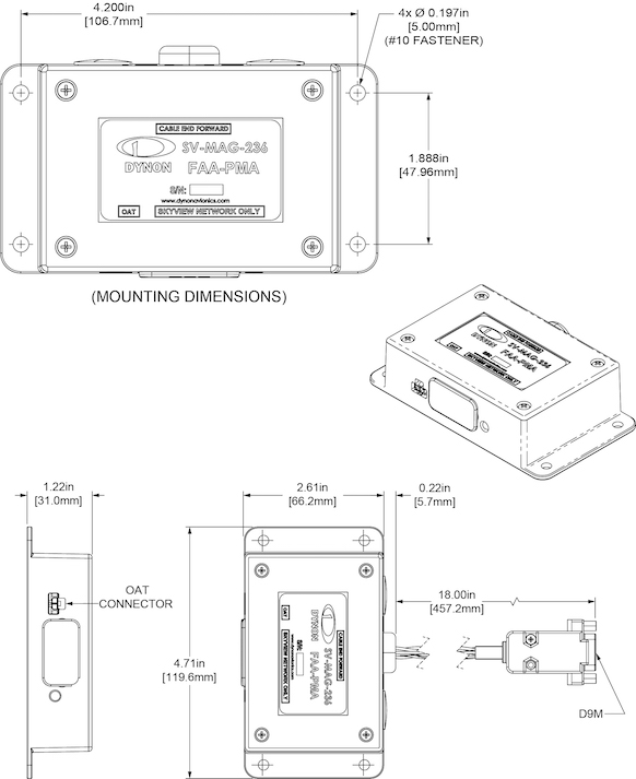
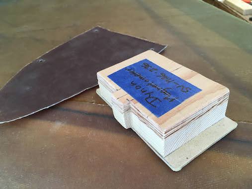 Here is my magnetometer mock-up and the Dynon dimensions and link.
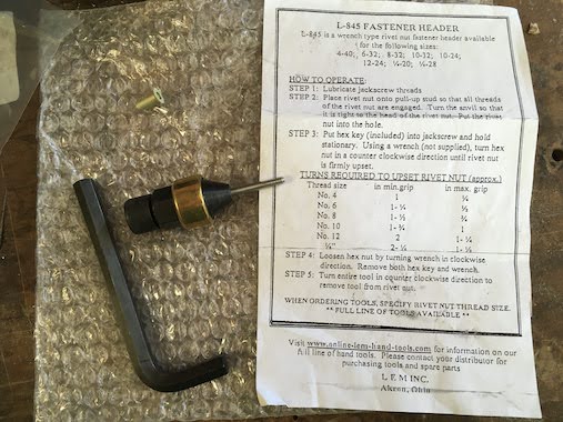 Here is the rivnut installation tool. It's nice that it can get into small spaces, the drawback is that it only works for one size rivnut.
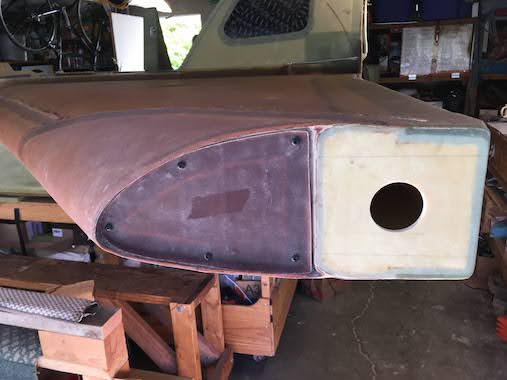
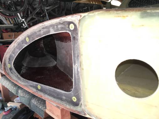 Here is the left side fairing block hollowed out and glassed with two plies of BID. I made a flox corner at the edge of the opening. It wasn't easy to get the glass where you wanted, pretty much had to do everything by feel since to reach the end was nearly the length of my arm. Only peel plied the glassed edges and where I will flox a pad for the magnetometer to mount to. You can see the lightening hole of the Outboard Diagonal rib which I used to establish the ceiling and floor of the hollowed out cavity. You can access even more space through that.
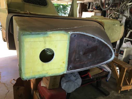
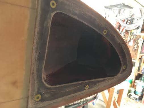 Here is the completed right side. The screws to hold the cover are brass.
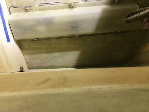
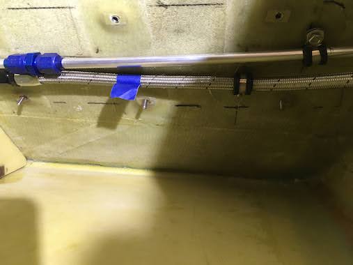 To make it easier to install the fuel line covers to the seat back I Loctited some threaded studs into the threaded 1/4" aluminum slugs. Now I can easily align the cover on the studs and attach with nuts on the bottom and screws on the top.
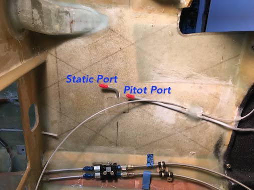
 Not really part of the strake but I decided to install the static port. This involves embedding a 1/4" tube into the side of the fuselage with micro and then after cure, drilling three 1/16" holes through the outside fuselage wall into the embedded tube. The tube is accessible on the inside of the fuselage to attach a tube connecting it to the displays for altitude. In the picture you can also see a second tube which is the pitot tube (a tube which extends from the nose of the fuselage) which provides dynamic pressure to the displays for airspeed, this was installed a long time ago.
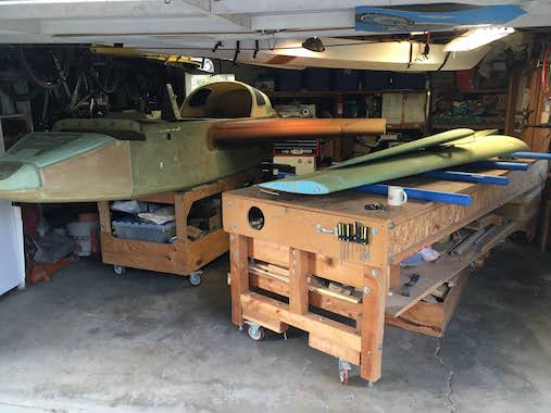 Well, 2023 is coming to a close, the year of the Strake. Have been debating what to do next. I feel like I should start the finishing of the fiberglass, filling and sanding so all the dust doesn't get into the avionics and engine. But I can't make the fuselage fairings until I have the engine cowls on, so it's a "Catch 22". I have ordered the engine from Aero Sport Power in Canada and will attend their Build School, hopefully May of next year and build the engine myself under supervision of course. So I think I'll put the winglets on the wings and do the rudders. I've been putting this off because once the winglets are on the wings take up a lot more space. But I have to do it sometime, so I rearranged the garage a bit moved the table and fuselage so I have a spot the winglet can extend up into the rafters where there's nothing already stored. Happy New Year!