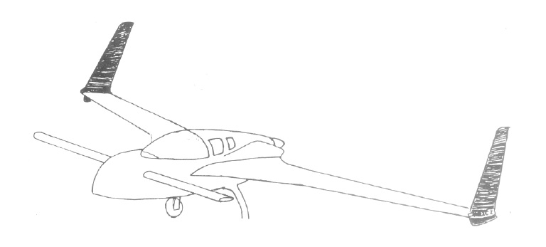
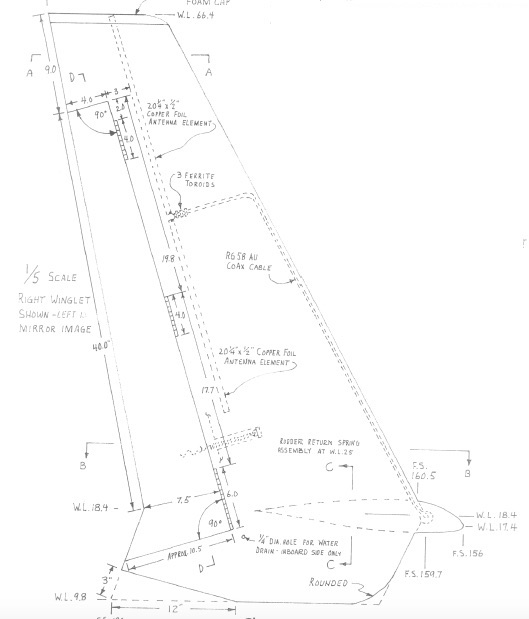
The winglets are the vertical stabilizers at the wing tips and also contain the rudders. These should be pretty simple to make the difficulty comes in making the hinged rudders similar to the ailerons on the wings. I'll also be doing the hidden bellhorn modification which adds some complexity.
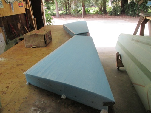
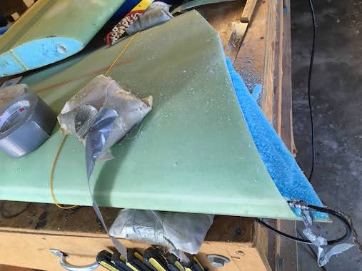
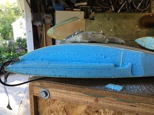
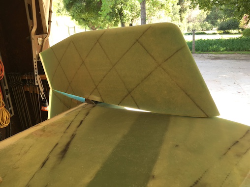
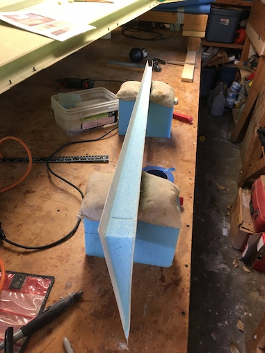
Here is the result of our hot wiring, pretty straight forward except that the airfoil template at the tip is much smaller than the template at the base which means the person at the tip is moving the hotwire very slowly while the person at the base is going as fast as possible. It gets tricky for the person moving slowly not to burn the foam. I set the voltage lower so the wire wouldn't be so hot. We got a little bit of burning but not bad, easy to fill with some micro.
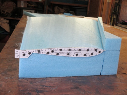
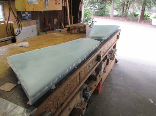
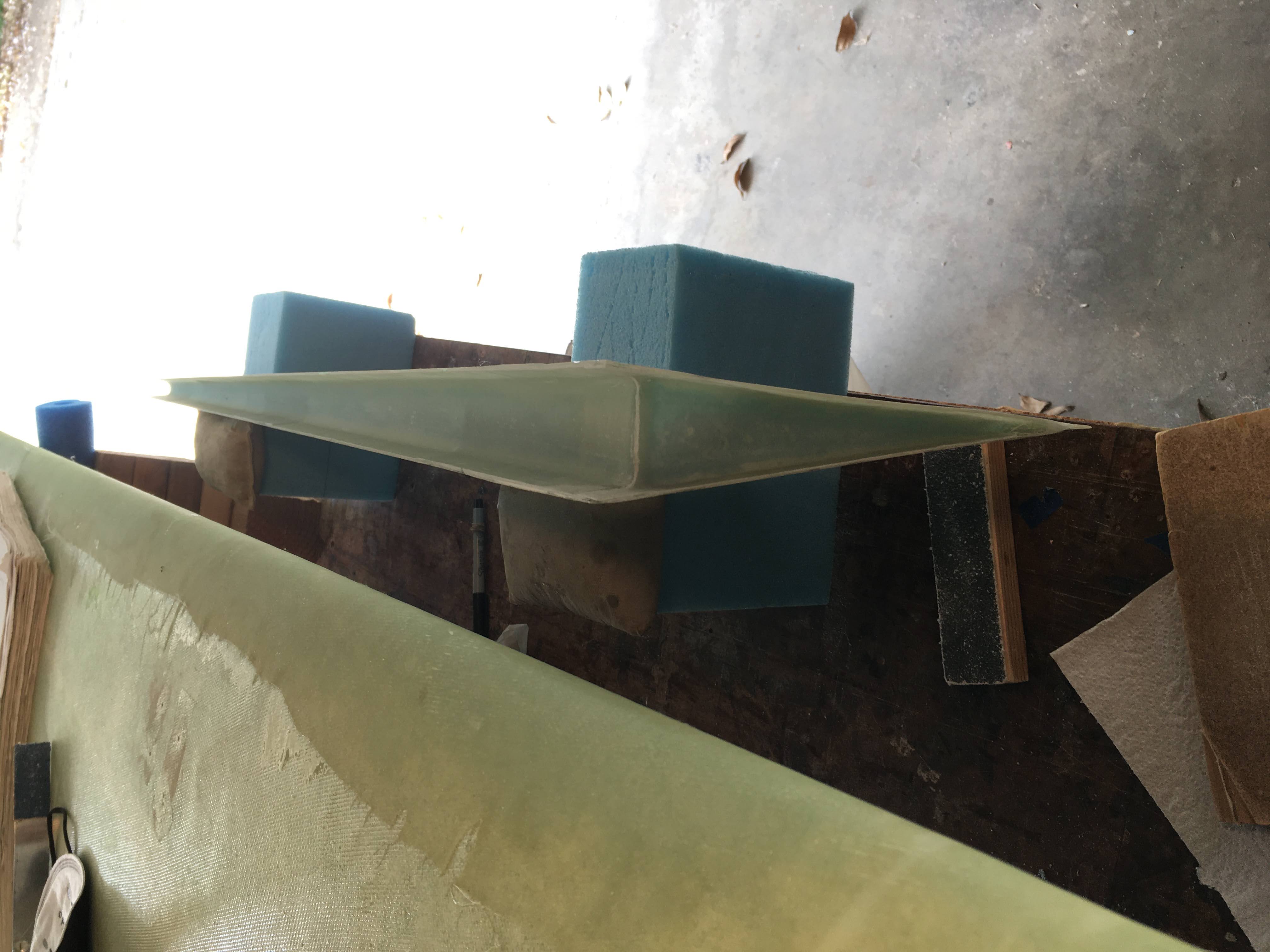
Here the foam cores are ready for the layup. The hotwired foam beds are bonded to the table with some micro/flox and then the foam cores are nailed to the foam bed to keep them straight. The second picture shows the foam cores mircroed.
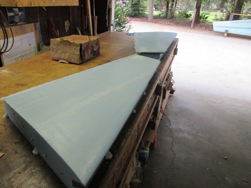
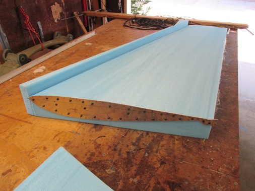
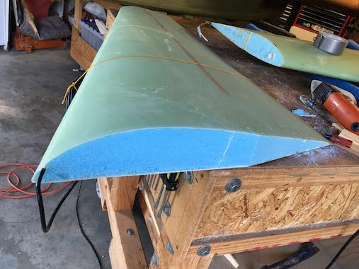
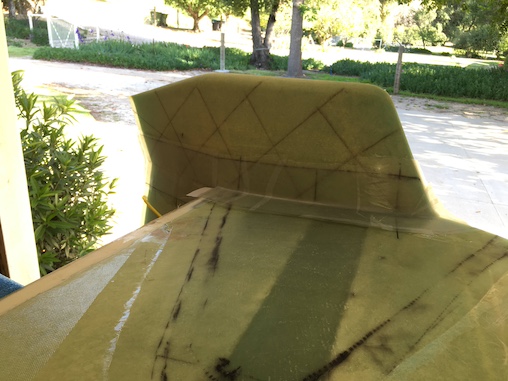
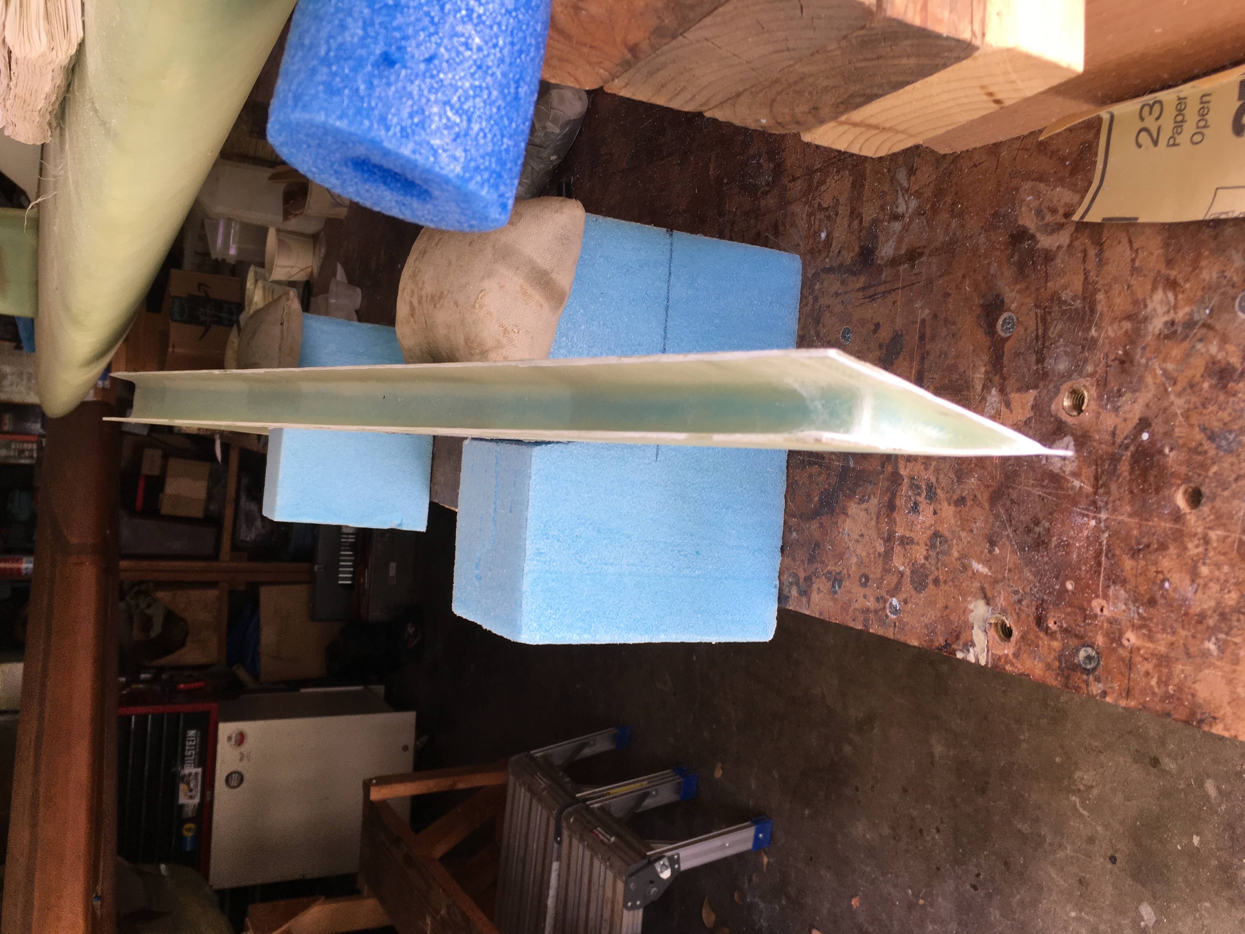
Here is the completed layup consisting of two plies of UNI angled corner to corner and a smaller ply of BID at the base.
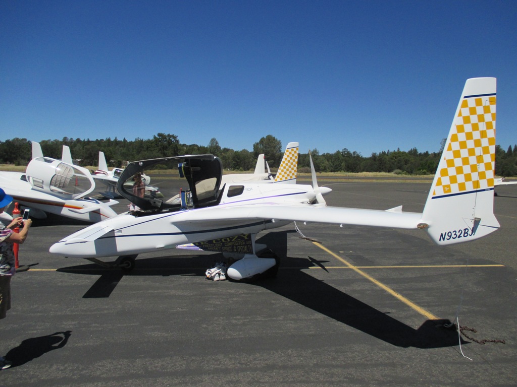
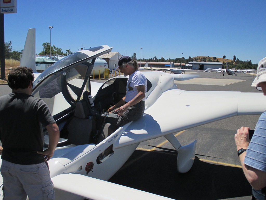
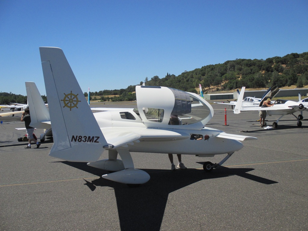
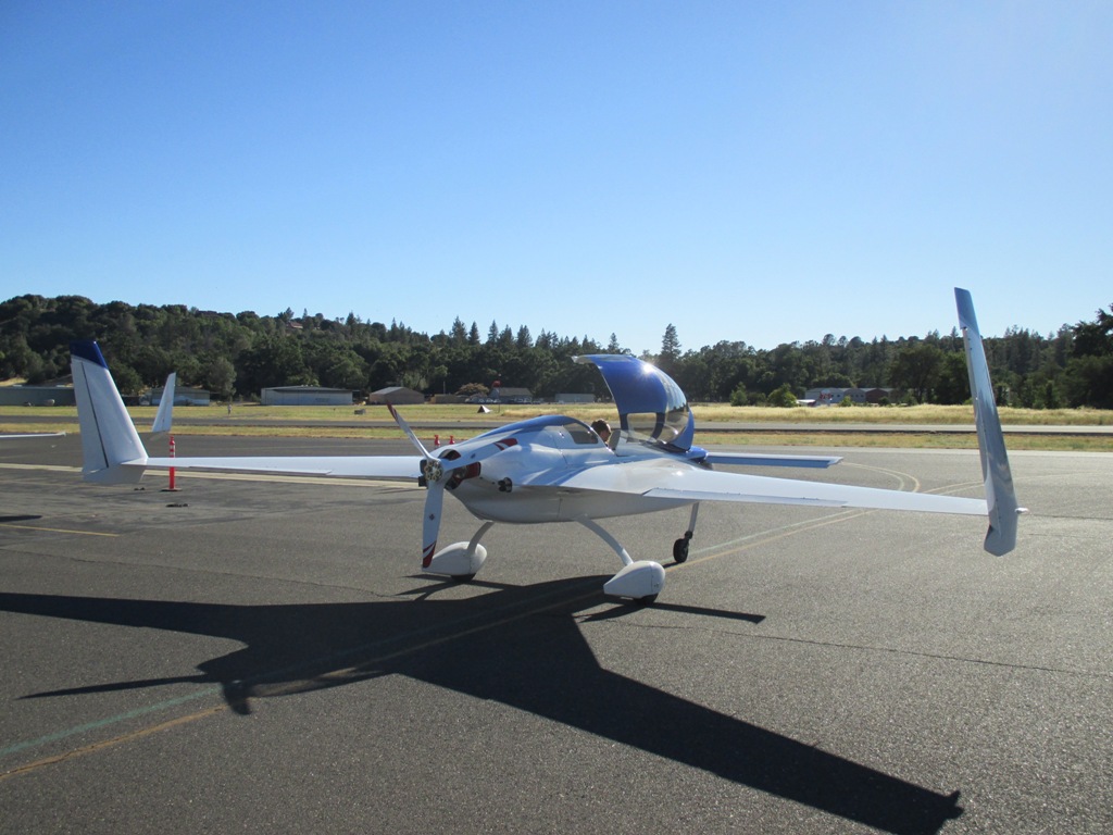
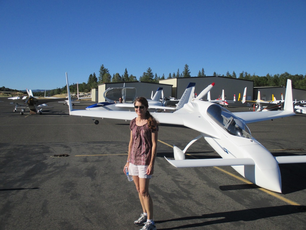
June 28 & 29 Columbia Canard Fly-In Photos.
Lynn and I went to the Columbia Canard flyin to get some inspiration.
Marc Zeitlin and his plane always answering questions.
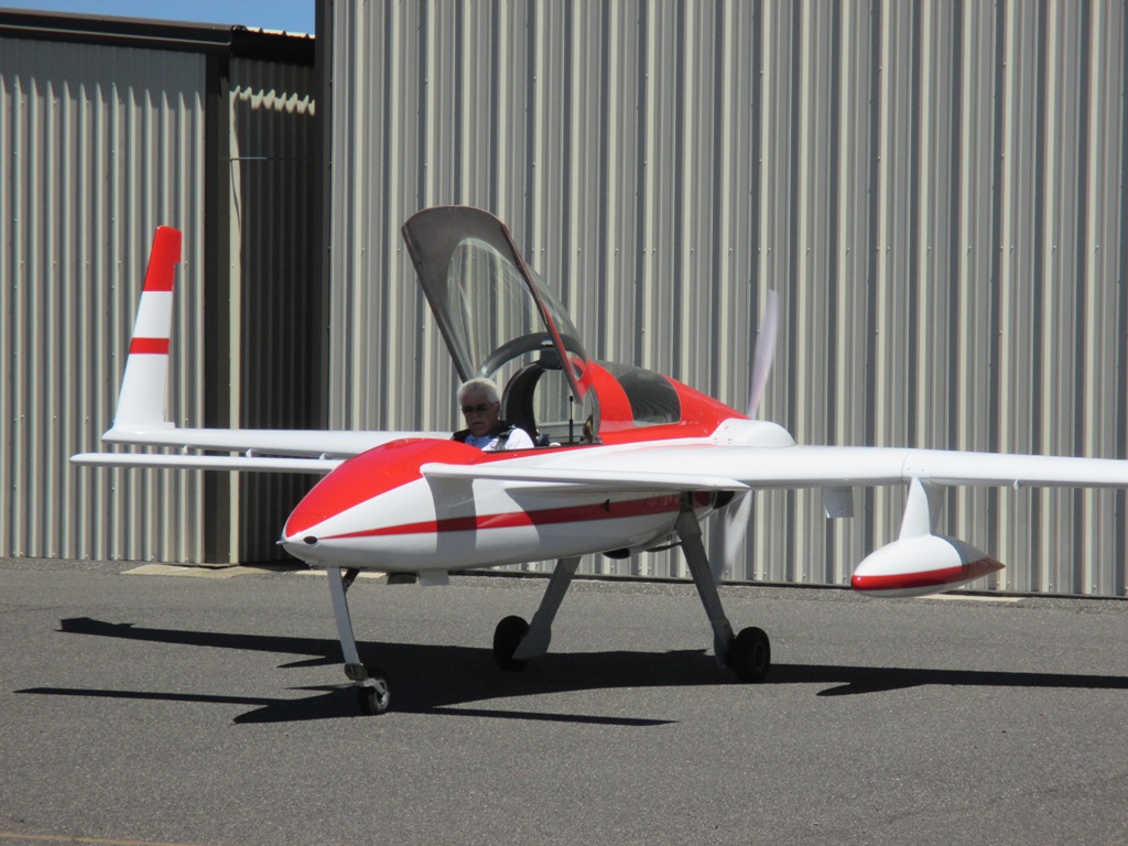
David Orr "Beagle" in his beautiful Berkut.
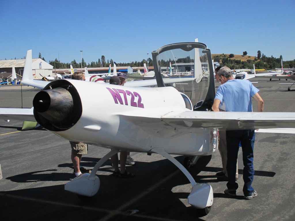
The Cozy Jet! - "Kerosene Dreams"
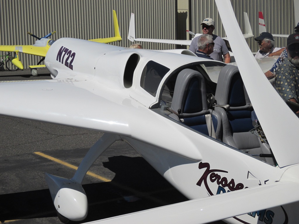
Lynn and I really like this Cozy MKIV.
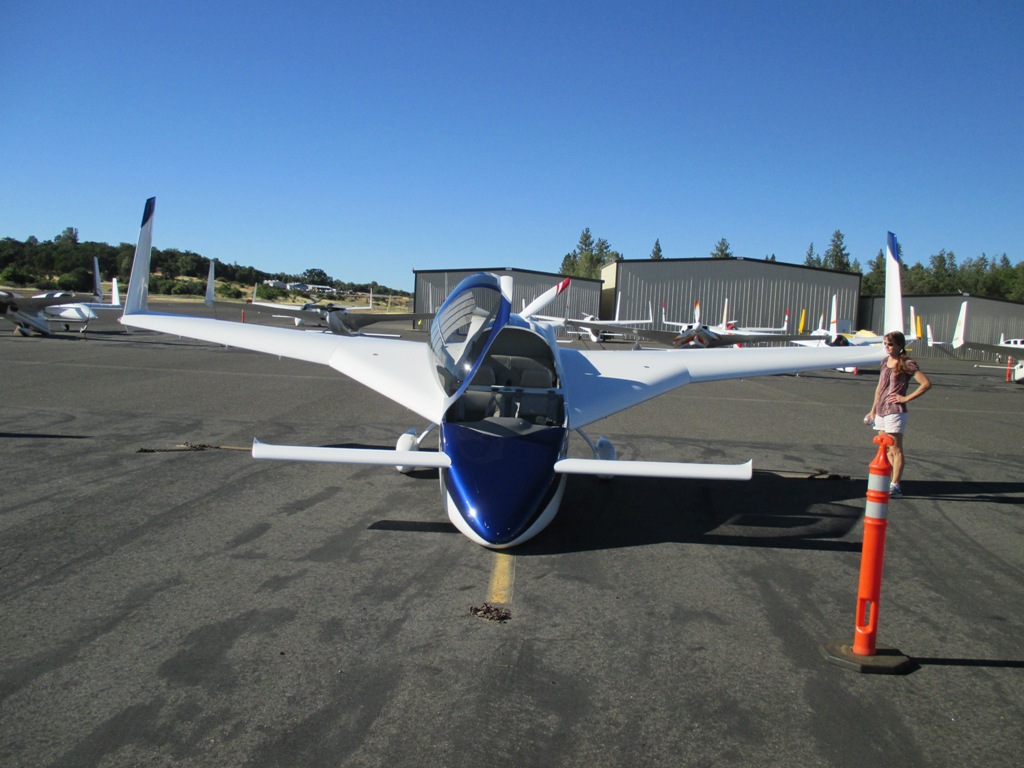
There was a good turn out of airplanes, probably 20+.
 So I've decide it's time to glass the winglets to the wings and cutout the rudders and make them functional. I'll be doing the hidden bellhorns so that will add a little complication but will look much sleeker without the external bellhorn. There's a lot to do and it's a bit intimidating.
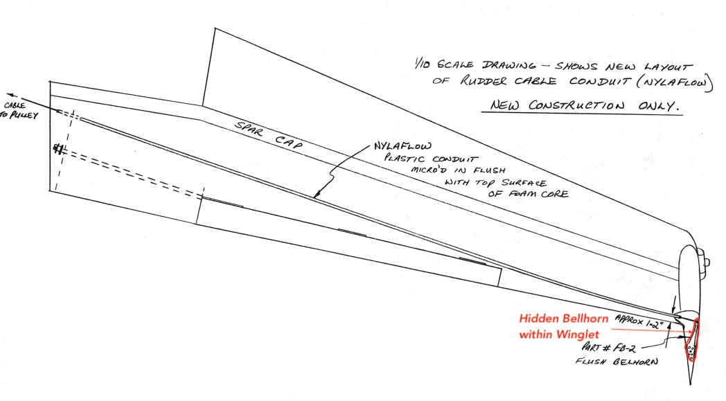
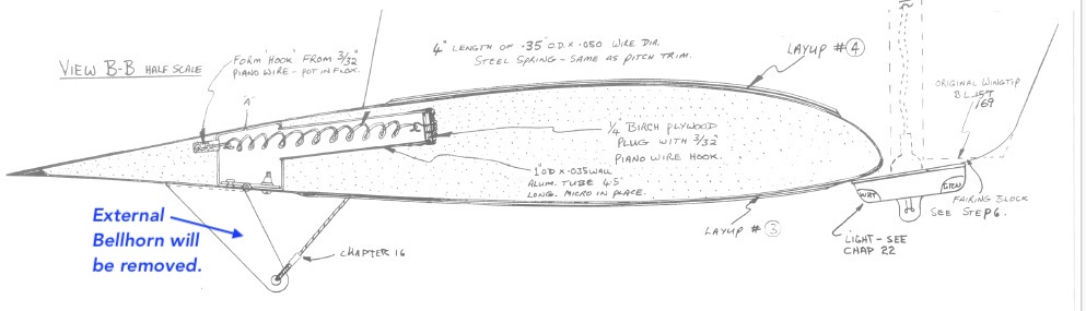
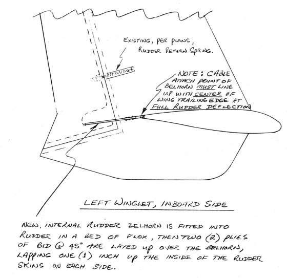 This is what the plans for the hidden bellhorns look like and are available on Marc Zeitlins website.
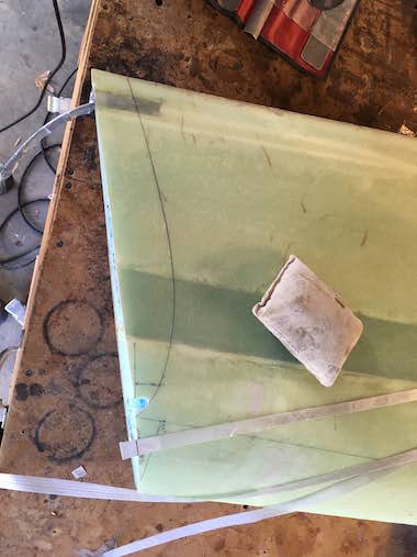
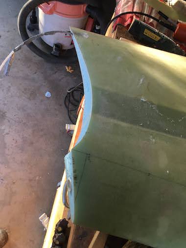
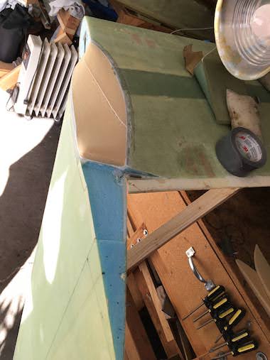
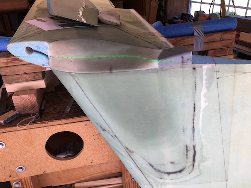
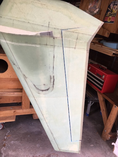
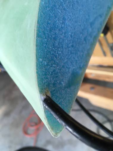 So you need to trim the bottom of the winglet to match the contour of the top of the wing and Drawing M-20 provides a template. Took some digging to find that, so I lined up the template with the hot wire level line and the base of the winglet as best as possible, didn't really match up very well and drew a line. The plans have you cut the piece out with a coping saw while keeping the blade vertical. I've never had good results with a coping saw. I decided I would cut through the winglet fiberglass skin with the Fein sander and then cut through the foam with a Japanese pull saw or sand to keep the cut vertical and then cut through the other side of the winglet skin with the Fein sander again. This worked perfectly. It was a bit touchy cutting near the coax cable for the COM antenna.
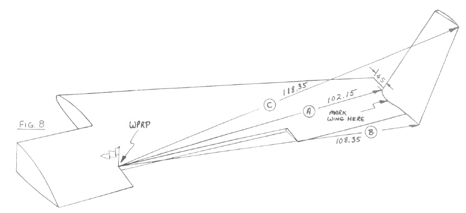
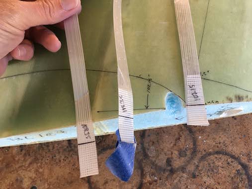
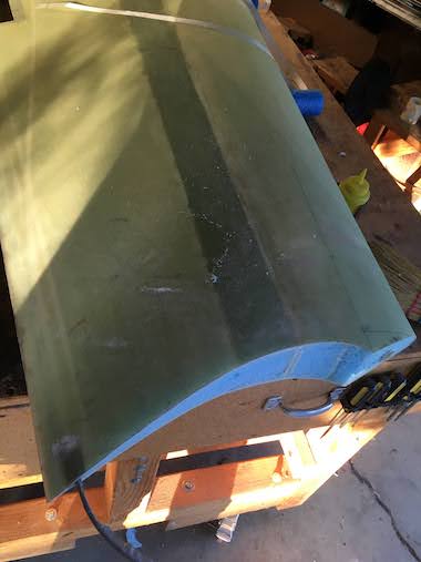
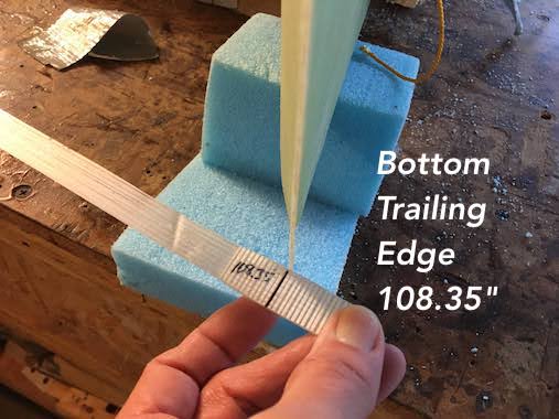
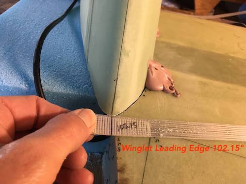
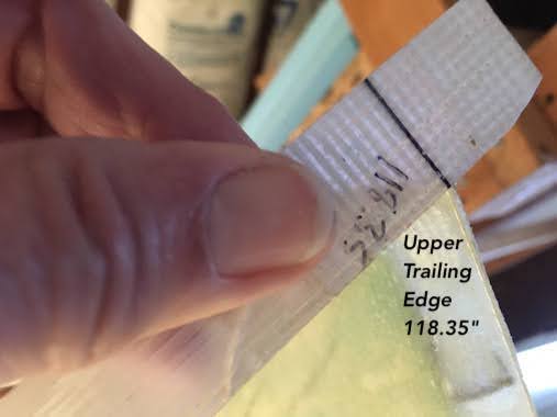
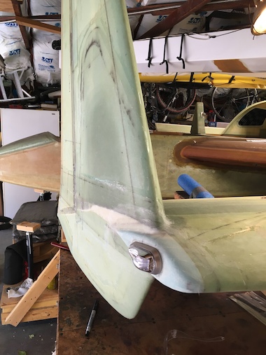
 So now I needed to trim the end of the wing to match the winglet. I bondo'd a nail at the front inboard aileron cutout as a measuring reference point per the plans. The measurements for positioning the winglet on the wing need to be within 0.05" except the top of the winglet can be +/- 1.0" which is how much the winglet is canted inboard. The plans have you use filament tape to make that measurement so you can tape the top of the winglet at the correct angle. I used filament tape for all the measurements because I could just run it through the bondo'd nail and make an accurate measure several times since the filament tape doesn't stretch. I had to notch the fiberglass at the wing leading edge to provide relief for the antenna coax cable so the winglet could sit flat.
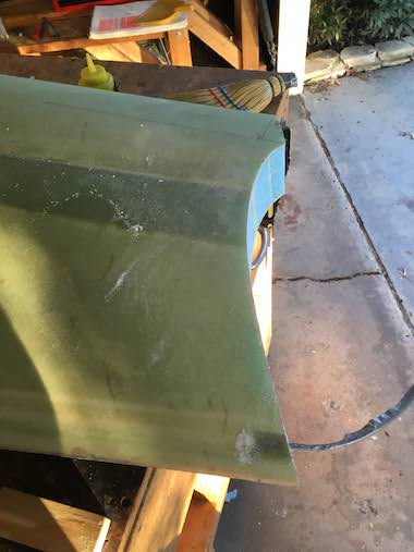
 Once the three measurements (winglet leading edge, trailing edge and tip) were confirmed Lynn helped to hold it in place while I drew a line along the inboard edge of the winglet onto the wing for cutout. I cut the piece out just like I did for the bottom of the winglet by using the Fein sander to cut through the fiberglass and the flush cut saw to cut through the foam. Also used a Dremel to smooth out the spar cap & web.
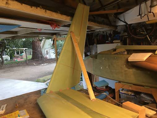
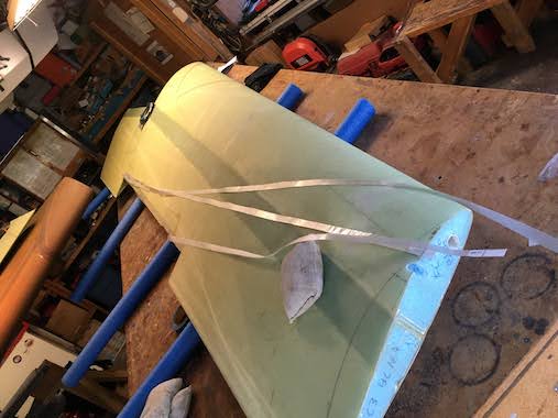
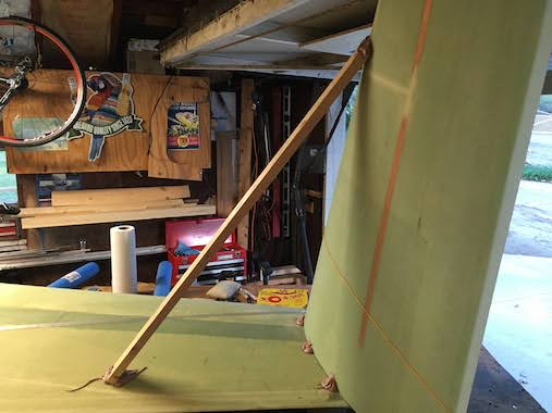
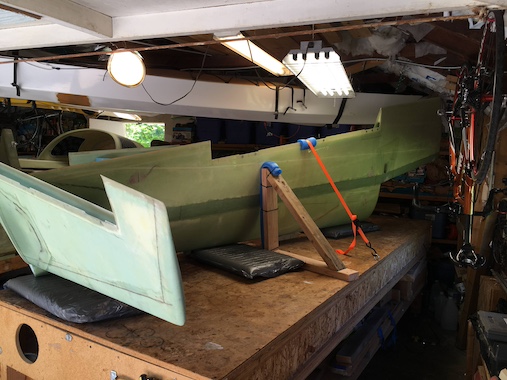
 I bondo'd the winglet in place on the wing supporting it with foam blocks and strips of wood. A 3 foot piece of would is also bondo'd as a brace.
 I doubled checked all the measurements before the bondo took a set.
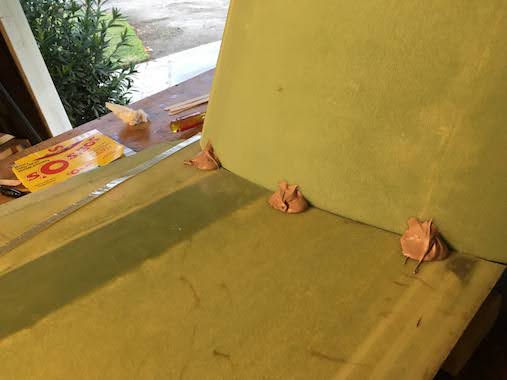 Bondo blobs.
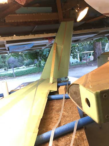
 I let the bondo harden overnight. The next day Lynn and I carefully flipped the wing over without breaking the bondo blobs and brace. Had some old wood to elevate the wing high enough for the winglet to clear the ground. Now I can do the internal layups which is nothing like anything I've done before. It looks simple when looking at the plans figures but in reality the layup is curved, so the wedges and foam block need to be curved and the antenna coax cable and rudder cable conduit get in the way.
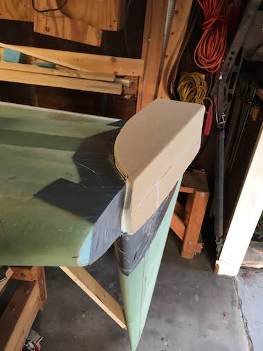
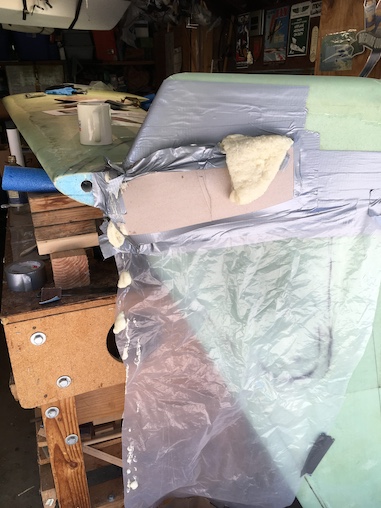
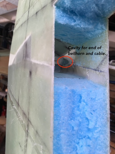
 Hogging out the foam for the internal layups and getting an idea how the internal bellhorn will fit with my cardboard mockup. I've ordered the internal bellhorns from the Cozy Girls but they're backed up with orders so I may have to try and make them myself.
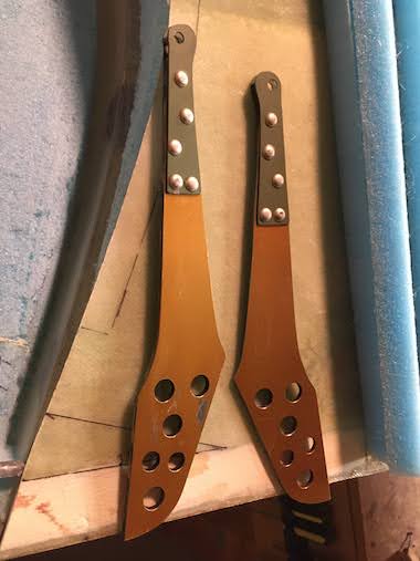 I made the internal bellhorns per the
Internal Bellhorn Plans. I was hoping to buy them from the Cozy Girls but they didn't have the lazer cut parts to make them. It would have been less expensive to get the bellhorns from them and excellant quality. But I think I did pretty good.
I made the internal bellhorns per the
Internal Bellhorn Plans. I was hoping to buy them from the Cozy Girls but they didn't have the lazer cut parts to make them. It would have been less expensive to get the bellhorns from them and excellant quality. But I think I did pretty good.
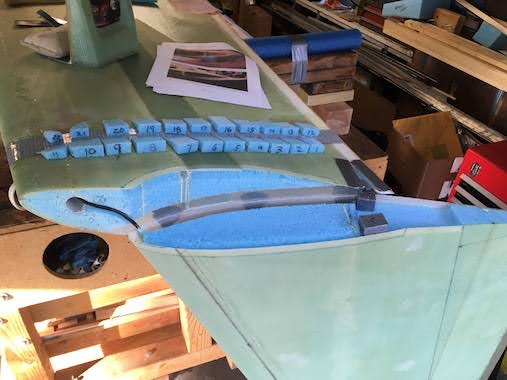
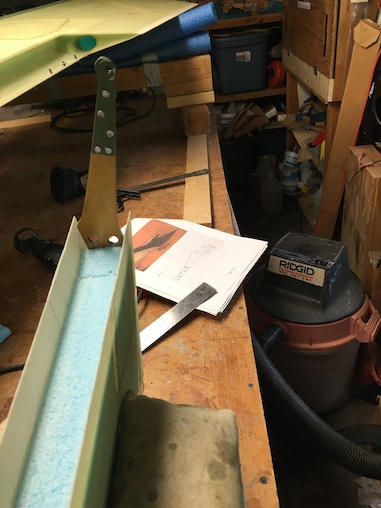
 I am following Joe Polenek's Perpendicular Internal Bellhorn Installation here is the plastic dam and bellhorn cavity cover made from report cover plastic. I made the foam wedges and numbered them so they'd be easy to put in place. The winglet and wing inner skins have been sanded and ready for glassing.
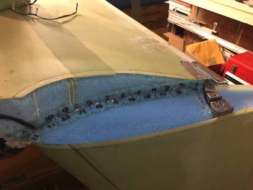
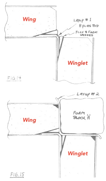
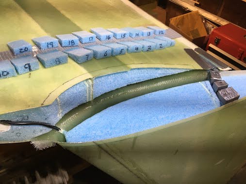 I've got the 9 plies of BID in place. That was a bit of a challenge but with a popscicle stick I was able to get it all flat and oriented correctly, this is layup #1. In the second picture you can see all the foam wedges floxed in place which keep the 9 plies of BID firmly pressed against the internal skins of the winglet and wing.
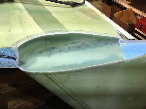
 After letting Layup #1 setup for about an hour layup #2, another 9 plies of BID was done. This also included floxing the corners.
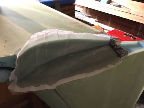
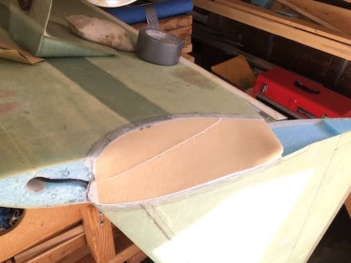
 Next was shaping a urethane foam block to fit in the cove. I made a cardboard template to get the curve at the top of the wing and then hand sanded to get a close fit.
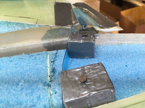
 Troweled in plenty of micro to ensure there were no air pockets when pressing in the foam block.
 Shaped the foam block per the plans except for the aft section which is kept level with the height of the bellhorn cavity per Joe Polenek's plans.
 Below are photos of finishing attaching the upper and lower winglet and cutting out the rudder. I'll add detail as time permits.
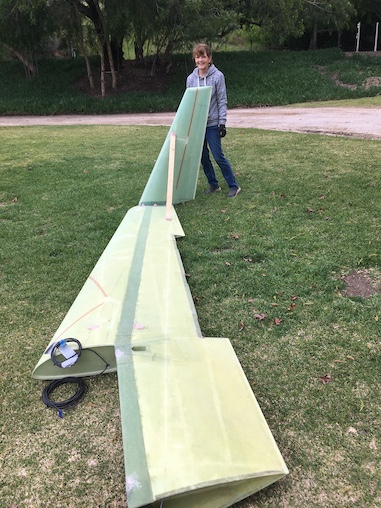
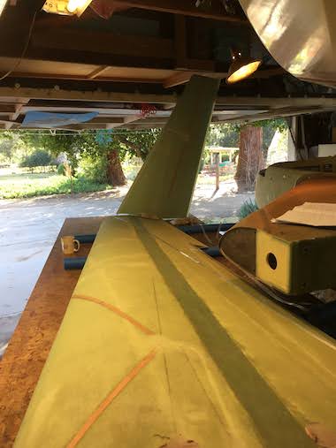
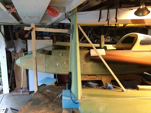
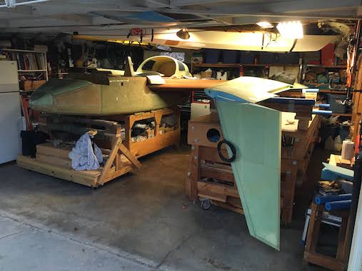
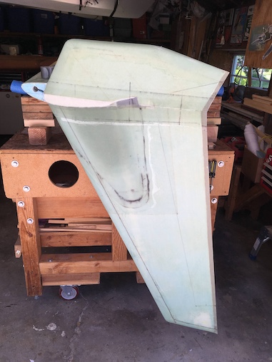
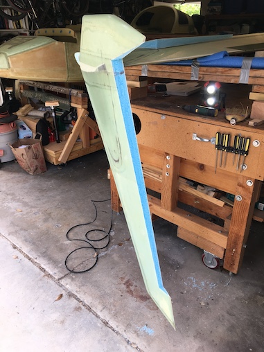
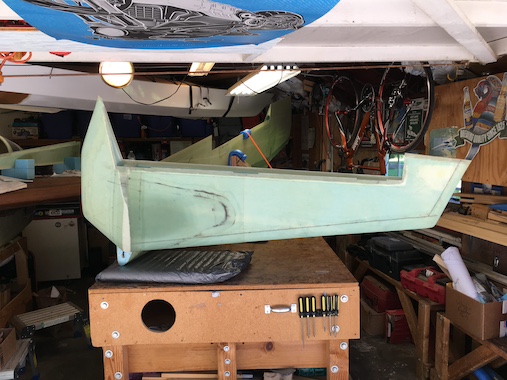
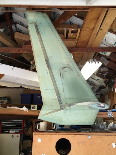
 Pulled the wing out to rotate it right side up. The winglet is pretty tall compared to Lynn who is 5'7". Also cleaned off the bondo blobs in preparation of the upper layup.
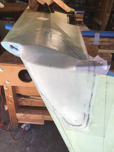
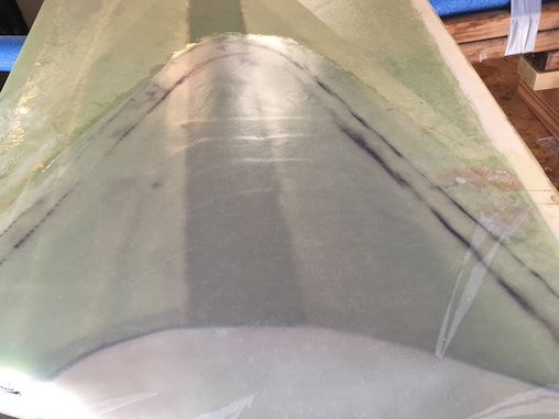
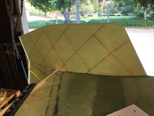
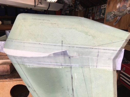
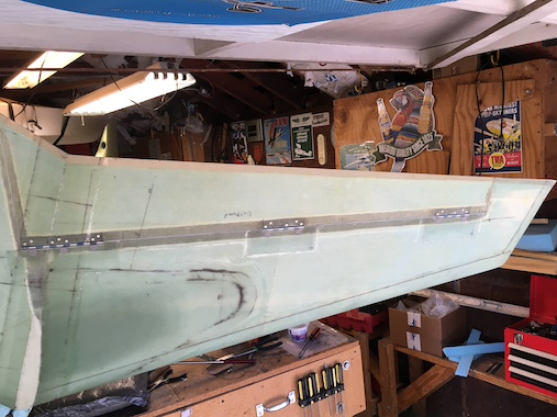
 Upper layup complete with 2 plies of BID and 7 plies of UNI all staggered. Used the laser level to figure out where the lower winglet would attach.
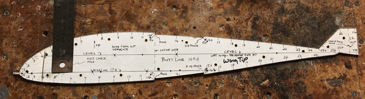
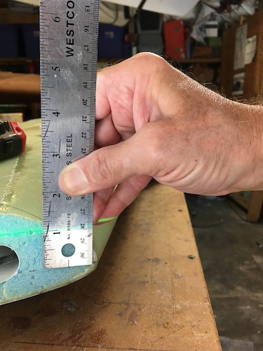 A lot of head scratching trying to figure out where to attach the lower winglet. The plans say to attach the root of the lower winglet to the wing at the 18.4" water level. I had no idea where the 18.4" water level line would be, but then figured it must be on the wing tip hotwire template. So I scrounged up the template and 1" above the 17.4" waterline on the template is the 18.4 inch waterline level with the trailing edge and 1" above the leading edge nose which I had marked many years ago when hotwiring the foam wing cores. So with the wing level and my laser level I could mark a line to match the lower winglet root to.
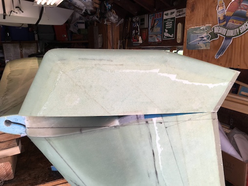
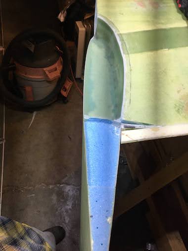
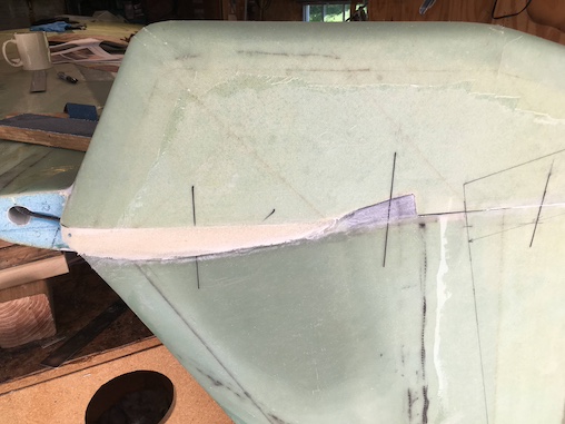
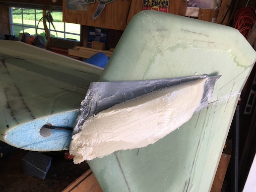
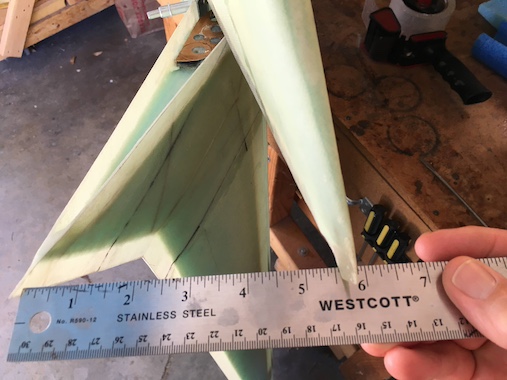
 With the wing upside down the 18.4" waterline is lower, but it gave me a target to shoot for in carving away at the lower winglet inboard side to get the outboard root at the correct level.
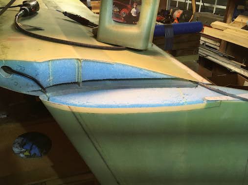
 As you can see a lot of the inboard side needs to be cut away to get the root at the correct level. I would cut a bit and check and cut some more until it finally fit.
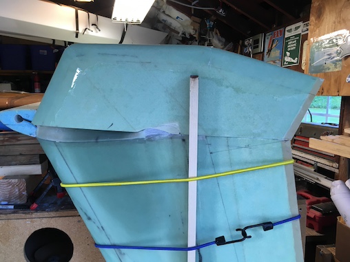
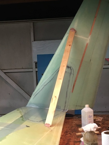
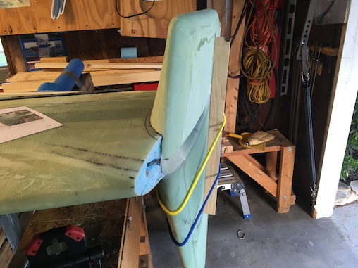
 I bungee'd a straight piece of wood to the upper winglet to align the lower winglet while glassing.
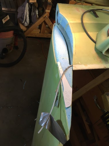
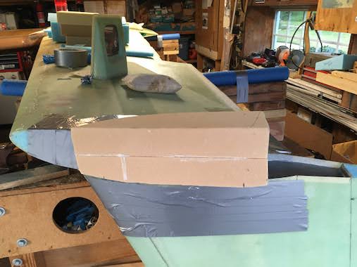
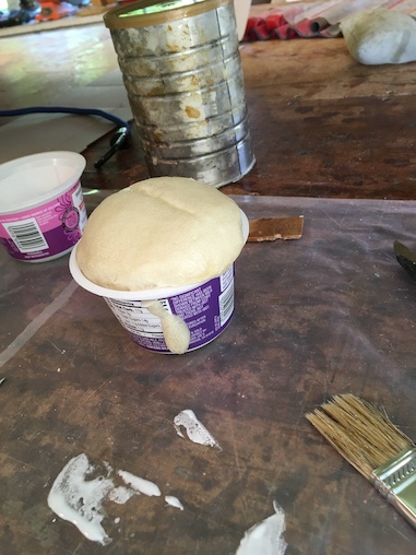 To fill in the gap between the upper and lower winglet I decided to use urethane pour foam, this stuff is always fun to use. I used a lot of duct tape and cereal box cardboard to contain the foam. It's amazing how much it expands which makes sure that it fills the entire space. Before pouring in the pour foam I micro'd the exposed blue foam at the root of the lower winglet, not sure if that was necessary but did it anyway.
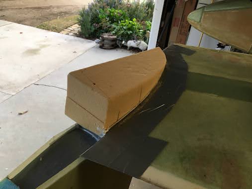
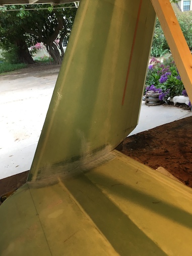
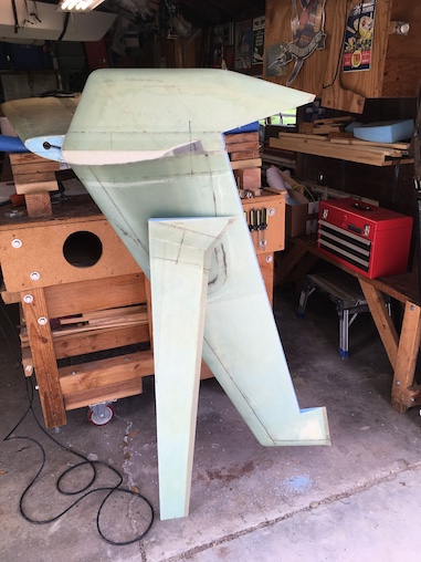
 I sanded the pour foam to blend the upper and lower winglets.
 I glassed the upper and lower winglets together with 2 plies BID staggered. The plans say 1 ply of BID but I thought that seemed a bit chintzy.
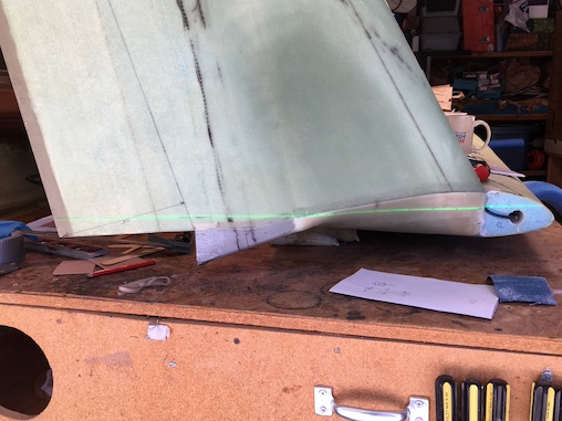
 More head scratching figuring out the rudder cutout lines. Joe Polenek's rudder cutout dimensions in Step 4. are a little bit different than the plans to provide for the additional depth needed to mount the bellhorn. I measured many times and my Rudder Cutout Dimensions came out slightly different than the plans mostly due to Joe's plans. Your dimensions will probably be different, I'm posting mine for personal reference. What's critical is getting the cutout lines the same on both sides of the winglet since you have to cut through the fiberglass on both sides, I used my Fein sander, and then complete the cut through the foam with a hacksaw through the cuts in the fiberglass.
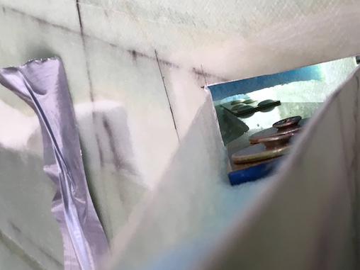
 I pulled out the duct taped plug to reveal the bellhorn cavity.
 Temporary fitting of the bellhorn to the the bottom of the rudder to determine final placement.
 Foam removed from the rudder to created a trough for a glass to glass channel which adds strength and hard points for hinge attachments.
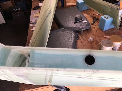
A view from the trailing edge of the rudder with the bellhorn attached to see what clearance the bellhorn has in the cavity.
 The rudder troughs glassed with extra plies at the hinge attachment points and flox corners.
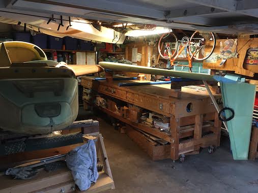
 The plans say to put the wing on your workbench leading edge down, always easier said than done. Made a fixture to hold the wing and put some eye bolts in the bench to strap it down. Had saved some foam shipping pads to put under the leading edge. The wood bench is great, you can attach stuff anywhere you want.
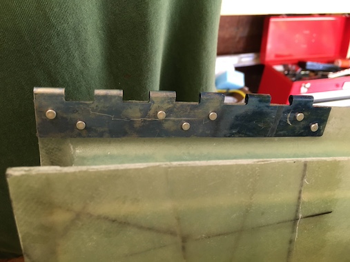
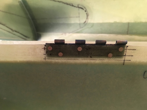
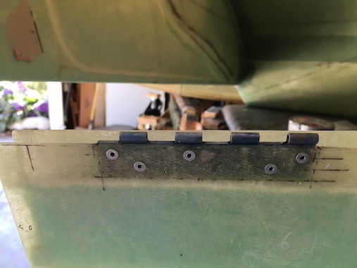
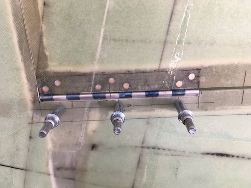
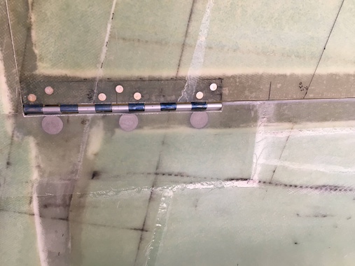
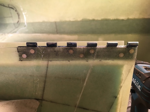 Riveted the hinge halves to the rudder with a rivet squeezer due to the space constraints in the rudder channel.
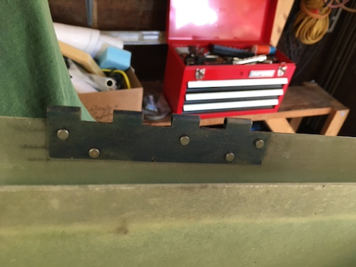
 The middle and top hinges are shorter.
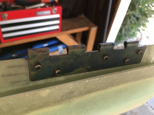
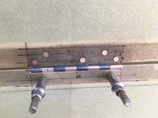
 I used pop rivets for the hinge half at the top of the rudder since there wasn't enough room for the rivet squeezer.
 On the winglet side the hinge locations need to be recessed to accommodate the hinge knuckle. The plans specify a 0.2 inch recess which is just enough clearance for the knuckle but results in a large gap between the rudder and winglet. I ended up having to close up the gap with flox and glass. On the left winglet I recessed more so that the gap between the rudder and winglet would be less. Per Joe's plans cleco's are used to hold the rudder to the winglet since it needs to be taken on and off so many times to trim to fit and verify travel.
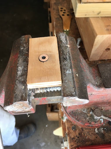 Joe recommends an AN111 bushing as opposed to a thimble due to it's smaller diameter allowing the end of the bellhorn more travel. The AN111 is just slightly thicker than the space between the bellhorn forks, so I made a little fixture (with some double stick tape on the bottom so it wouldn't spin) to hold the bushing while I filed it down so it would fit nicely between the bellhorn forks. Joe bent the bellhorn forks slightly to accommodate the thicker bushing.
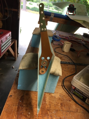
 The bellhorn screwed down in position with some 5 minute epoxy flox tabs to locate it per Joe's plans.
With bellhorn held in position the rudder travel can be checked to make sure you're getting the maximum possible.
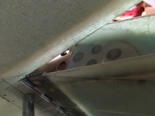
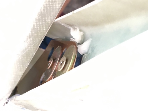
The first picture shows the bellhorn floxed in position and the second picture shows it glassed in. The third picture shows the clearance with a nutplate that I ultimately decided against and went with click bonds instead.
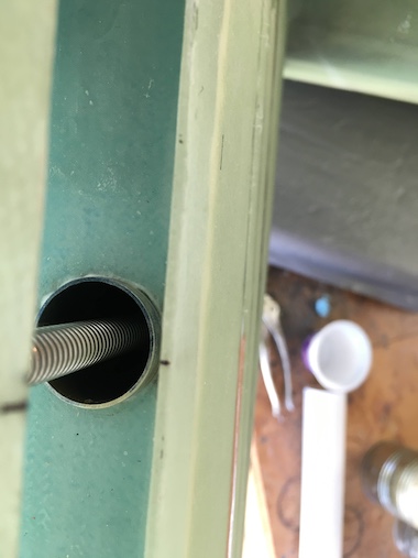
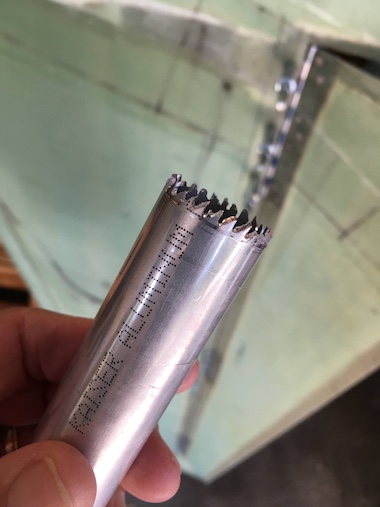
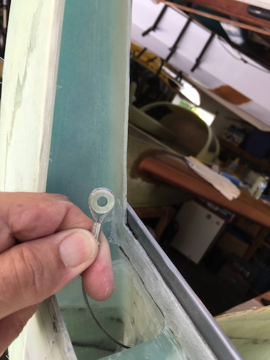
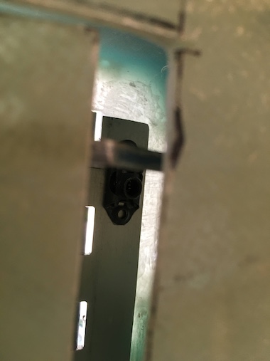
These pictures show the installation of the tube and rudder return spring into the winglet. This installation is per the plans. I first dremeled out the glass for the hole and made a tubular saw to cut out the foam. A tube with a hook at the bottom is micro'd in the hole. There's an associated hook floxed into the rudder. The spring is hooked on, which is a pain, to return the rudder to faired position after deployment.
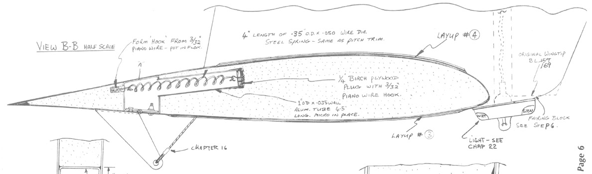 Sorry I don't have any pictures of how I made the hooks but the hook in the end of the tube is held in place by a birch plywood plug and the hook in the rudder is floxed in place. The 3/32" piano wire is really hard to bend some blood was shed.
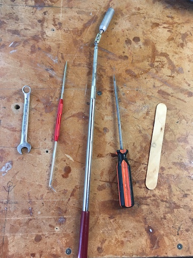
 I've finished the installation of the click bonds for fastening the winglet side of the hinge half. I got really lucky with the clearance between the bottom click bond and the bellhorn. Here are the special tools needed to install and remove the rudder from the click bonds.
I found a tip on the Cozy email group for installing the rudders with click bonds that it's easier to install the winglet hinge half first with the nuts loosely fastened. Then line up the rudder with it's hinge halves set in the winglet hinge halve and slide the hinge pins in. Now push the winglet hinge halves against the winglet and all that's left is to tighten the nuts. Most of the battle is getting the nuts started in the tight space between the rudder and winglet.
I somehow inherited a wrench where the box end was heated and bent at a 45 degree angle which is the only way to tighten the nuts in the tight space in the top hinge. I did have to grind down the outside diameter of the box end wrench to make it thinner. The popsicle stick is to pry the winglet hinge off the winglet when removing the rudder without damaging the winglet fiberglass edge. The magnetic tool is for getting arrant nuts. The huge dental pick is for attaching the return spring and the screwdriver is for pushing the winglet hinge half over the click bonds.
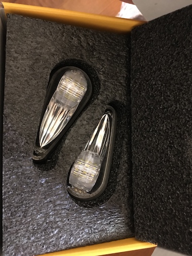
 The only thing left to do to finish off the wing/winglet join is the wing tip lights. I bought the TSO'd version of the AeroLeds, which were a couple hundred dollars more expensive than the experimental version. At the time there was a lot of communication on the email group about whether you needed TSO'd lights or not and one person's Cozy was ramp checked by an FAA inspector and was cited for not having TSO'd wing tip lights which would make it illegal to fly the airplane at night or IFR. Now as I write this it seems more people feel non-TSO'd lights are fine. There are other brands that offer wing tip lights that are much less expensive than the ones I bought but these seem to be of very high quality.
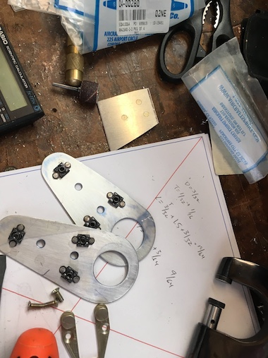
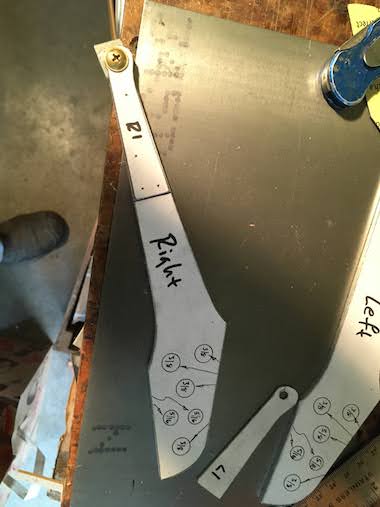
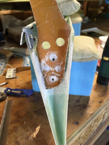
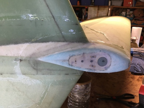
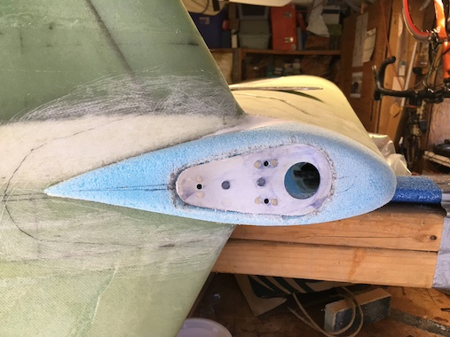
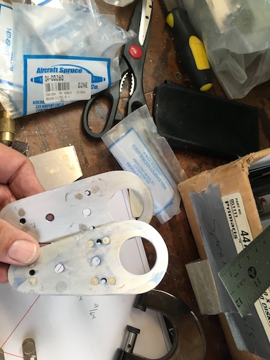 The first thing to do is make some mounting plates to mount the wing tip light bracket to. I made the mounting plate a 1/16" proud of the actual base of the light to provide for a bit of misalignment. I riveted floating nut plates to match the hole locations of the wing tip light bracket. The two large holes in the mounting plate are to lock the plate in position with flox.
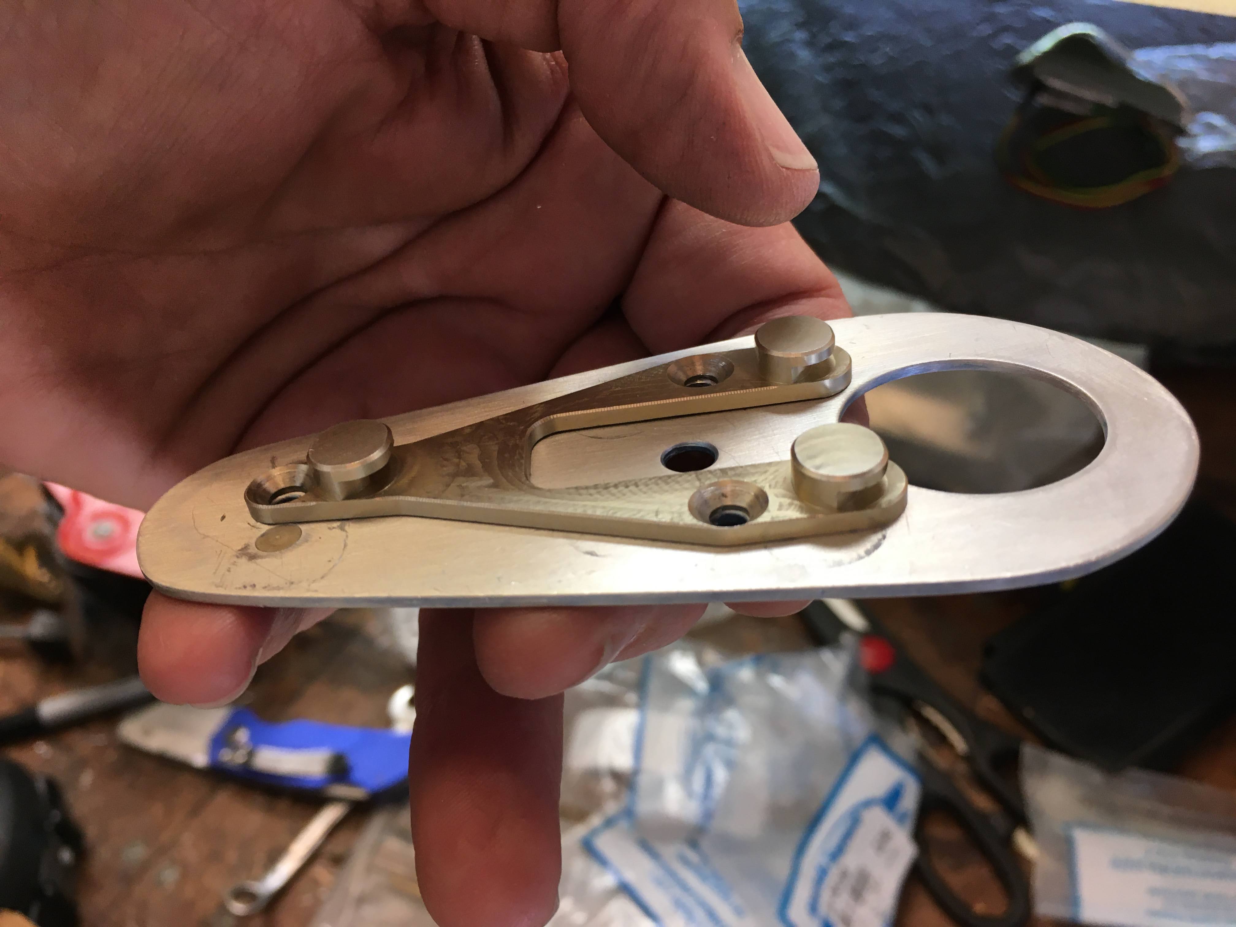
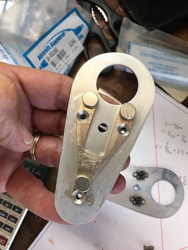 Here you can see how the bracket will attach to the mounting plate.
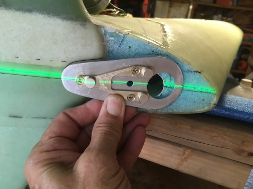 Using my laser level to figure out where to position the wing tip light.
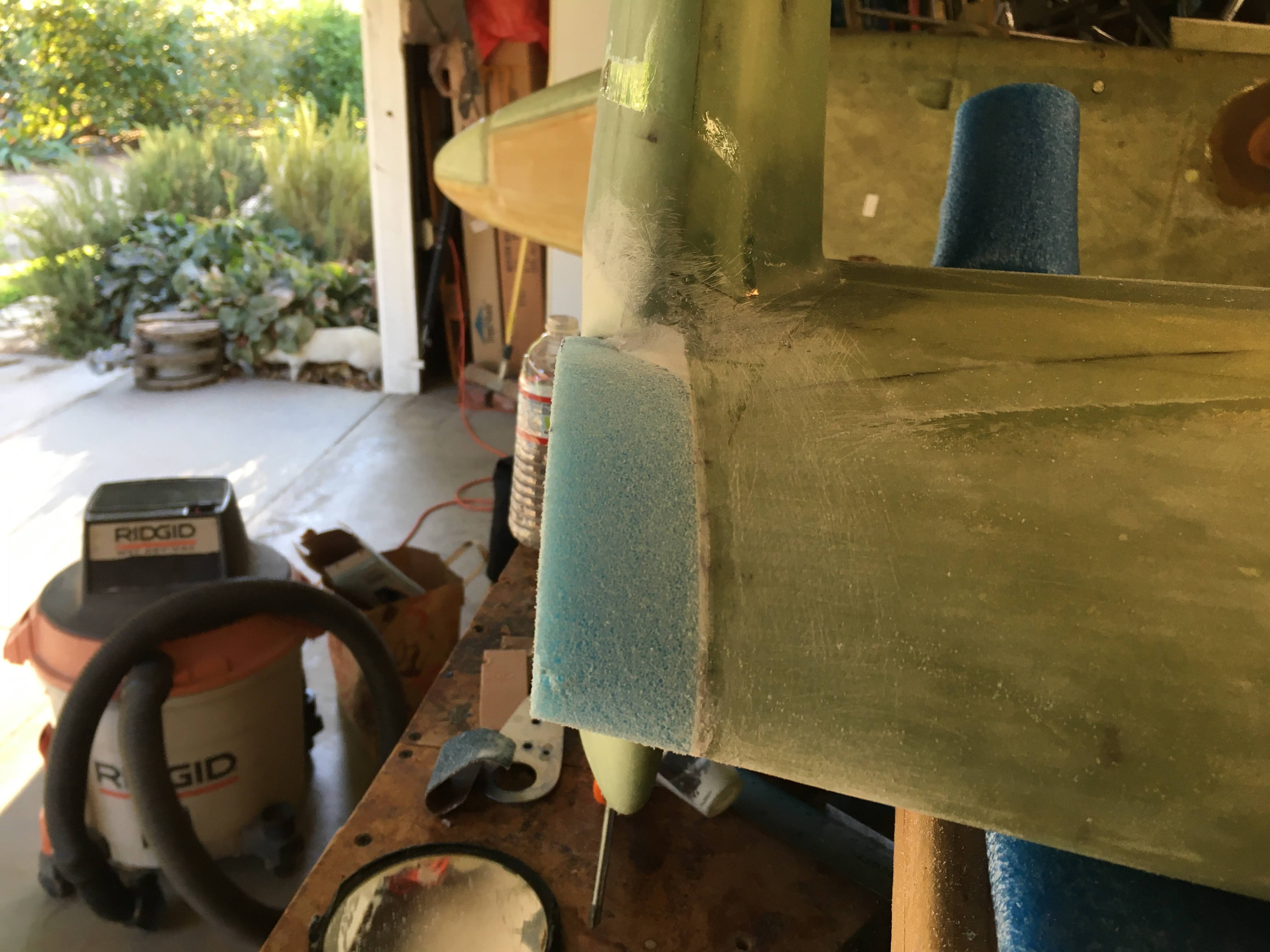
 Added some foam to the end of the wing tip so the light would be outboard of the winglet.
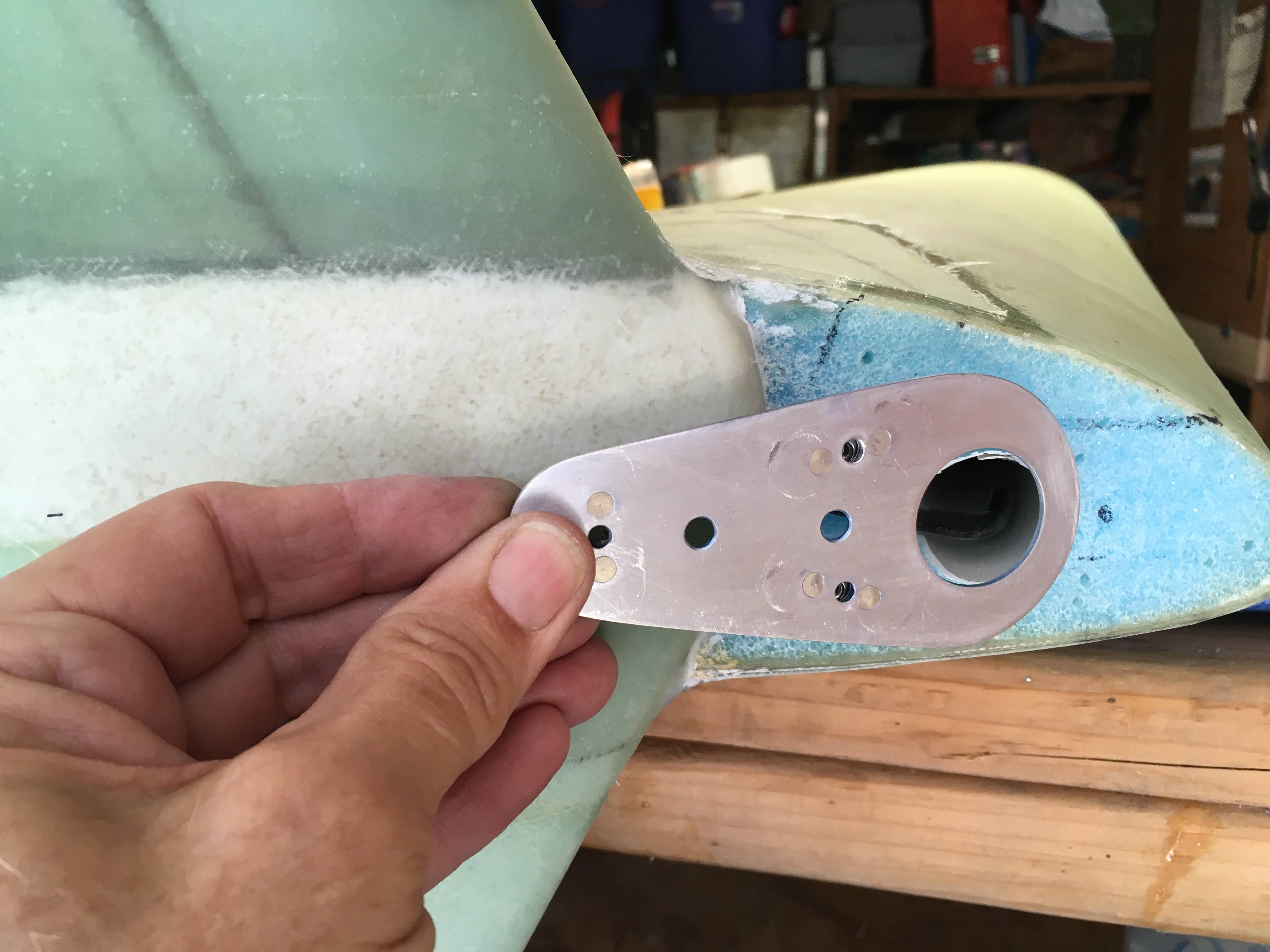
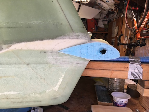
 Recessed the foam for the mounting plate and made it into a pleasing shape. The mounting plate was floxed in place and then the whole thing was glassed with two plies of BID. After cure I opened up the mounting holes and electrical conduit hole.
 I'm pretty happy with how it came out for someone with no artistic skills whatsoever.
Now to do the left side, oh boy!