Chapter 4 Bulkheads
Sunday Sept. 8, 2002
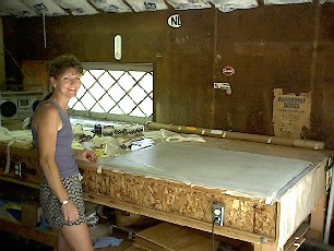 Yahoo I'm making real airplane parts, with the help of my wife, Lynn. She really saved me, I'm happily wetting out the first ply of cloth thinking I'm ready to put on the next ply and suddenly realized that I didn't cut any more cloth, uh oh. Lynn to the rescue, she cut out the cloth, mixed up four more batches of epoxy, inspected the layup, found some bubbles and wetted out the peel ply. Hmm, maybe I should stand back and keep the epoxy pump full.
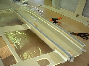
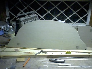
After the front side of the seatback cured I cut all the notches for the fuselage side longerons, the top ones are kind of tricky. Just really need to take your time, use the templates and draw lines on the top, sides and bottom. I used a little Stanley pull saw to make the cuts and then sanded to the line. The 1 inch holes were done on a drill press with the help of my brother-in-law Erik, it was a bit awkward with the drill press table set at a 45-degree angle, but it worked out OK. These will probably be reworked once installation of the aileron torque tubes takes place.
The plans call out flox corners anywhere the two sides of glass meet, which means all four edges. It was a bit of work to cut out the foam and grind the micro off the glass. You have to be careful that you don't grind through the glass. After querying the Cozy email list I found it's better to leave a little micro and not thin the glass. So, do the best you can without killing yourself. Carl Denk recommended a 1/8 inch Dremel carbide cutter, picked one up at Home Depot but haven't tried it out yet. The backside of the seatback took me about four hours to do even though it was only 1 ply of BID. Filling all the flox corners took a while and micro slurrying the foam took some time as well. One goof up was when laying up the front side I bondoed the foam to the table so that it would be flat (most of the foam seems to be warped). After the front layup cured I popped it off the table no problem, the bondo pops cleanly off the masonite, but I had to chip it off of the foam leaving some pretty healthy divots. Which wasn't any real problem I could just fill with dry micro, but what you're supposed to do is use very small dabs of 5-minute epoxy to hold foam to masonite which limits the size of the divots to something very small. The bondo is used to temporarily hold down cured glass to masonite. Live and learn, oh well now I have some white blotches on the back of my seat back, it will get painted and no one will know.
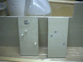
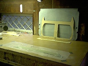 I also started on the F22 and F28 bulkheads. To transfer the lines of the templates on to the foam I used Jerry Schneider's idea of a serrated tracing wheel for sewing. It pierces the paper and puts small perforations into the foam which you can then mark with a Sharpie. I also used Rick Maddy's technique for gluing the foam pieces together with the duct tape hinge method, see his website for the step-by-step procedure. The foam for these bulkheads is Last-A-Foam it is whitish yellow in color and only 0.20 inches thick. It is much denser then the blue foam and I wondered how applying the micro slurry to this type of foam would be. So I did the layup for F28 first, since it's pretty small. The layup went fine, 2 plies of BID and 1 ply of UNI, you don't end up with much slurry in the foam since it is so dense, but when you look close you can see the micro is indeed filling the foam cells. I also opted for the more rounded shape of F28 following the dotted lines on the template. I think I followed the dotted lines further than I needed to because my F28 has ears on the ends. I don't remember anyone else's looking like this, no biggy, I can cut them off later when I'm sure they're not needed.
Sunday Sept. 15, 2002
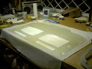
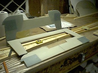
 Did the layups for F22 and the instrument panel. FYI, the doubler for F22 does get micro slurry on both sides even though the plans only mentions putting slurry on the aft side. When in doubt always following the basic education spelled out in chapter 3. Nat and the Cozy email group answered this one for me without giving me a hard time, it is so nice to be part of such a great group of people. The forward face of F22 was pretty interesting with the buildup of plies on the outboard uprights, 4 plies of BID alternating with 5 plies of UNI, all those extra plies of glass cause the outside edges to have a darker color. I peel plied the entire F22 bulkhead and the instrument panel just because it's easier than dealing with the peel ply tape. The peel ply leaves the surface finish smooth which is nice for the instrument panel but I actually like the weave look of the cloth, it gives it a more rugged look. I think there also might be some controversy as to whether peel plying results in a heavier or lighter part. I think (and so does Burt according to his video) that peel plying will result in a heavier part. If you squeegeed the layup per the instructions where there is no ridge of epoxy when you lightly drag your squeegee across the layup then you have the correct ratio of epoxy to glass (50/50). If you peel ply the layup you're supposed to add epoxy to wet out the peel ply otherwise the peel ply will soak up epoxy from the plies below which will cause your layup to be epoxy lean. So my take on this whole peel ply issue is that if you peel ply per the instructions you will have a heavier part because the epoxy used to wet out the peel ply will also fill the weave of the cloth. If you don't wet out the peel ply and allow it to soak up epoxy from below you will have a lighter part because that epoxy will be removed with the peel ply, but you run the risk of having an epoxy starved layup. It seems with the MGS epoxy, because of it's low viscosity it wets out easily and doesn't take much squeegeeing to get an epoxy lean layup. Therefore I need to wet out the peel ply to avoid a lean layup and by wetting it out it fills the weave of the cloth resulting in a heavier part. I'll have to weigh my parts and compare with archived weights. My plan will be to peel ply only where necessary to avoid sanding for subsequent layups. Here are some pictures of the instrument panel and F22. The Fein sander was really amazing in trimming the 9 plies of glass on the edges.
Saturday morning, on the recommendation of a new internet acquaintance, David Orr, a local EZ driver and organizer of canardian type events, I went down to Santa Monica airport (SMO) to meet up with some Long EZ fliers and builders. I thought I would bring some of my practice pieces and finished parts (seatback & F28) to see if I might get some constructive feedback like, "you might want to take up gardening". Before I knew it I was talking with Dave Ronneberg, designer of the Berkut. He basically told me that I was doing a good job and to keep on building. He also said there's probably nothing more difficult or rewarding in life than building your own airplane and no matter how many airplanes he builds the current project is always the most difficult because of new ideas he's incorporating to improve performance. His shop/hanger is filled with beautiful molds for the fuselage and wings. He redesigned the wing and developed a new construction method which eliminates the solid foam core and and uses carbon fiber in the spars to make it stronger and resulting in a wing that weighs a mere 60 lbs. Because of the slow down in the economy he has had to discontinue sales of the Berkut but made certain that he fulfilled all the orders he had. I was just blown away that someone of his caliber would take the time to look at some googly eyed beginner's bookend and say, "hey, nice flox corner." There were two or three other people building Berkuts in Dave's shop and as he was looking over my seatback they obviously looked perplexed. Dave could see their confusion, because there are no fuselage parts on a Long Ez or Berkut that are that big and quickly dispelled the mystery and said, "it's for a Cozy". Anyway I came away from that meeting both intimidated and inspired.
Sunday Sept. 29, 2002
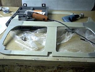
 Finally finished the instrument panel with all those nasty little
"L" shaped stiffening ribs. I used 1-inch square (cross section)
strips of wood covered with duct tape to form the vertical
layup that creates the wire channel. I made some triangular
supports to hold the wood strips in place. It was kind of tricky
clamping the triangular supports in place and on the stiffener
above the leg cutouts I couldn't figure out a way to do it.
So I bondoed them in place. I could bondo directly to the panel since it had peel ply on it and the bondo held fairly well to the duct tape on the wood strip. This worked perfectly, it stayed in place and after the
layup cured the triangular supports popped off no problem.
Finally finished the instrument panel with all those nasty little
"L" shaped stiffening ribs. I used 1-inch square (cross section)
strips of wood covered with duct tape to form the vertical
layup that creates the wire channel. I made some triangular
supports to hold the wood strips in place. It was kind of tricky
clamping the triangular supports in place and on the stiffener
above the leg cutouts I couldn't figure out a way to do it.
So I bondoed them in place. I could bondo directly to the panel since it had peel ply on it and the bondo held fairly well to the duct tape on the wood strip. This worked perfectly, it stayed in place and after the
layup cured the triangular supports popped off no problem.
I did this a little differently for the
vertical stiffeners on the center post. There I covered the glassed foam vertical stiffener with duct tape and 5 minute epoxied the wood
strip directly. The 5 minute epoxy holds pretty well to the duct tape. Later while the layup was curing I was a
little worried that I wouldn't be able to get the wood strip out
because of the limited space, I left it alone and let it cure.
After it cured the freshly layed up glass bonded itself fairly
well to the duct tape as well and it seemed like I would have trouble getting
the wood strip out, but with some careful prying with a paint
spatula the wood strip was liberated.
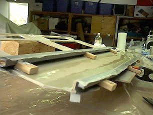
 I also did the massive layup to create the material for the landing gear bulkhead hardpoints. Here you can see all the precut plies of BID ready to go. The plans say that it will probably require 22 plies to achieve the � inch thickness, but essentially it needs to be � inch so that it is the same thickness as the foam that makes up the core of the rest of the bulkhead. So my plan was to make a wood frame, � inch thick that would sit around the perimeter of the layup, (it ended up being slightly thicker than a quarter inch only because I got tired of sanding it down while maintaining a uniform thickness on all four sides, I also figured it would be better to err on the thick side), that way once all the plies of glass were layed up I could put a straight edge across the wood frame and verify that the layup was thick enough. I believe I ended up with 26 plies, kind of lost count. Well, when all was said and done, measuring with calipers it ended up being 0.31 inches thick. This presented some problems as you�ll read below.
So I moved on to the landing gear bulkheads. I cut the hard
points out of the 26 ply (in my case) layup using my band saw.
The first 3 or 4 cuts went pretty easy, then I noticed it was
becoming increasingly more difficult to cut on a straight line. I
tightened up the blade a bit and that helped but I think as
the blade dulls it becomes more reluctant to cut straight. I cut
everything a bit proud and straightened the edges on the belt
sander. Because my hard points ended up thicker (0.31 inches) than the 1/4
inch thickness of the foam I debated whether it would be better to center the hardpoint on
the foam and have equal excess thickness on either side or have it flush on one side and have all the excess harpoint material on the other side. So I queried the Cozy email group, Marc
Zeitlin recommended flush on one side and all the excess on the other. The reasoning was to have
it flush where the landing gear would be bolted in to prevent any
interferences. I beveled the side of the hardpoint which would
stick out to make the layup easier and 5-minute epoxied the hardpoints to the landing gear bulkhead foam. I put the micro slurry over the foam and also made a dry micro
fillet, at the edges of the hardpoints so the glass would transition over the hardpoint without any air gaps. But on one edge no matter how hard I stippled and pressed
it always seemed that there was trapped air in the layup. Also, all the stippling with epoxy resulted in the dry mirco not being so dry anymore and just spreading out and floating away. I let the layup
cure and pulled up the peel ply and it didn't look too bad,
probably acceptable but I wasn't happy. So I thought I can fix
this in about 2 to 3 hours work or I can be unhappy every time I
look at it for the next 5 to 6 years. So I took a file and filed
away the offending glass and tapered all the sides of the hard
point to a very gradual slope so the glass would layup easily. I
was lucky in one respect because I didn't realize on the aft
bulkhead, the vertical ends are supposed to get extra plies of UNI
reinforcement during this layup, not like the forward bulkhead which
gets them later when it is installed in the fuselage. Since I
hadn't done that yet I only had to file through the 2 plies of BID
and one ply of UNI. After adding the plies for my repair and
adding 3 plies of UNI (for aft face) to the vertical ends I read the
instructions
more thoroughly and realized that the aft bulkhead is supposed to get
2 plies of BID and 2 plies of UNI over the entire bulkhead, not
like the forward bulkhead which only gets one ply of UNI. So I
added another ply of UNI over everything. I don't believe that
having this one ply of UNI on top of everything instead of as part
of the initial plies should make much difference to the overall
structural integrity of the part.
NOTE: While writing this, I emailed Nat Puffer, the designer, just to be sure there would be no structural problem; I figured no one else would know better. Within 15 minutes he responded back and said that it would be OK, no one has busted a landing gear bulkhead yet despite the hard abuse. Also the UNI that is layed up horizontally should only be on the horizontal portion of the bulkhead putting it on the vertical sections doesn't add any strength, only weight. Wow! Can you imagine getting support like that from anywhere else! I am just amazed, with all the help and support you get from the designer, builders, flyers and the entire canard community I know I'm going to finish this plane! Thanks Nat!
Oh, by the way the Fein sander is really working out great. It takes a little getting used to, at first I didn�t like it. But trying to catch layups during the knife trim stage was becoming impossible and even that method leaves a lot to be desired. After reading the email archives, how everybody was raving about the Fein Sander and since I spent $180.00 for it I thought I better learn to use it. When you�re cutting with it, it is extremely important that you keep the blade parallel to the edge you�re trimming because before you know it you�ll be cutting right into the foam. Cuts can be made easier by how you have the semicircular blade positioned on the tool. Once you get the hang of it you can make precise cuts but I still leave about a 1/16 inch of excess glass and sand that down to the foam. I also thought that my initial difficulty was due to the standard cutting blade that comes with sander. Fein also has a better blade made from High Speed Steel (HSS), expensive too, $90.00 for a pack of two, which is meant for fiberglass cutting, so I ordered that as well, I'm into it deep now. In the meantime I�ve been using the standard blade thinking it wouldn't last long but it�s actually holding up and working well. The sander and it�s accessories are available through Coastal Tool. The only other ways I know of to trim cured glass is with a jig saw or bandsaw. I've heard that the up and down motion of a jig saw can pull the glass and disbond it from the foam. The bandsaw would probably be better but these large pieces would be awkward to maneuver. So I'm real happy with the Fein sander, some people building their second composite airplane can't imagine that they ever got along without it.
Sunday Dec. 1, 2002
Well it's been awhile since I've posted any progress, but I believe I'm finished with Chapter 4. I cutout the "real" firewall pieces from the 1/4" Norwegian plywood (really nice wood). Alodined (for corrosion prevention) the aluminum inserts for the engine mount hole locations and installed them into the sqaure cutouts in the plywood.Covered one side of the plywood with a single ply of BID and then on the other side I drilled and countersunk the holes for the screws that hold the rudder pulley brackets. Debated for awhile about what to do about the screw turning issue that's been brought up on Cozy Builders email list but just went with the plans method and ground a flat on the screw head and floxed them into the countersunk holes. After the flox cured I sanded the flox flush and covered this side with a ply of BID. Even though the screws look like they're floxed in solidly and won't turn they probably will and cutting a slot in the end of the screw isn't such a big deal. The slot will allow a screwdriver to keep the screw from turning while tightening the locknuts that hold the pulley bracket.
My first real Oaf Story! Marc Zeitlin coined this phrase as a way to highlight the stupid foul-ups that inevitably occur in a project of this nature. To finish up the chapter all I had to do was drill some 1/4 inch pilot holes in the Forward Landing Gear bulkhead hard points, which later get drilled out to 3/4 inch holes for the landing gear attach bushings. Well it had been awhile since I even looked at these parts and I drilled the holes into the Aft Landing Gear bulkhead by accident. Amazing how I always double check everything after the deed is done. The aft bulkhead holes aren't supposed to be drilled until after installation into the fuselage and they are not in the same location. So, the only thing I could think of doing to salvage the bulkhead was fill the holes with flox. You can just barely see the filled in holes in the picture (the aft landing gear bulkhead is the one standing up in the background). Flox is structural so it should retain the structural integrity of the part especially of such a small hole which will probably get drilled out anyway when I drill the 3/4 inch hole for the bushing. Just to make sure I emailed Nat and he said that the flox would be a good repair. Lesson learned, label every part no matter how obvious you think it looks.
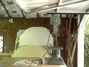 Got some new equipment for my shop. My brother-in-law, Erik managed to save an old drill press from the Fire Dept.'s machine shop that was being excessed. He was able to bring the runout back into acceptable limits. This thing has some major girth to it, over a hundred pounds, and I have it on the workbench for now since I have absolutely no more room left. I may build a rolling stand for it since I know I'll be needing the entire workbench space for building the fuselage sides.
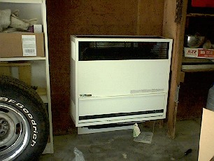 Even Southern California winters don't keep the garage temperature above 75 degrees F, so Erik and I installed a gas heater. Tapped into the natural gas line in the house and ran the plumbing into the garage. Erik has all the tools to cut and thread the metal pipe and it was quite a job. The heater has a double walled duct that goes through the wall of the garage. The inner duct brings in the air for combustion and the outer duct is the exhaust. The coldest outside temperatures when I'm working is 50 to 60 degrees F and the heater brings the garage temperature up to 75-80 degrees F in about twenty minutes. After a layup I'll keep the heater turned On for at least 4 hours until the parts have cured appreciably. Thanks Erik for all the help!
To most other builders it must seem like I'm pretty slow, but I'm far exceeding my own expectations. The only reason why I started at all was that I figured it would take me a year to build the bulkheads and they wouldn't take up much space in the garage. Now a little more than three months later I'm done with the bulkheads and ready to move on to Chapter 5, the fuselage sides, these are going to be some major pieces. Actually I've already laminated the longeron spruce stringers together, but anyway I'm getting ahead of myself, you got to click on Chapter 5 to see that. Garage space is going to be a major issue in short order.
Return Home Chapter 5