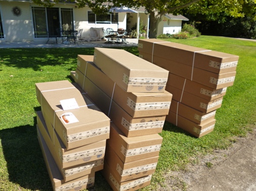
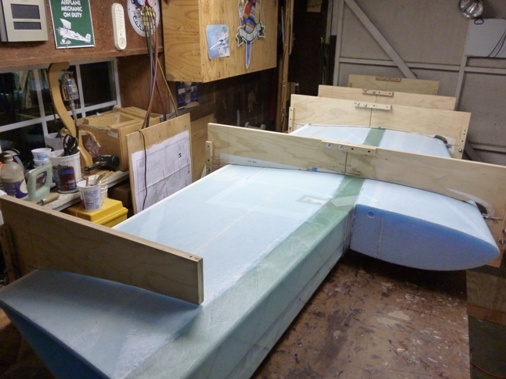
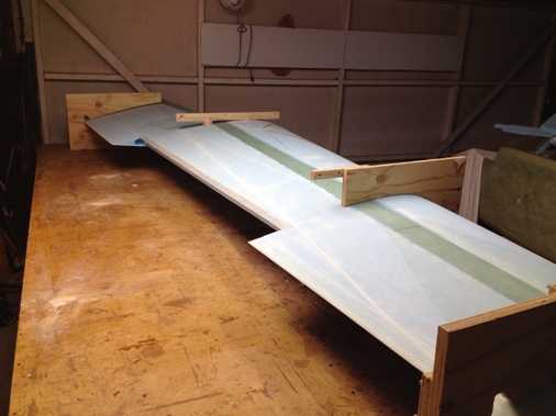
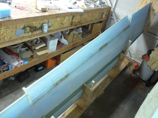
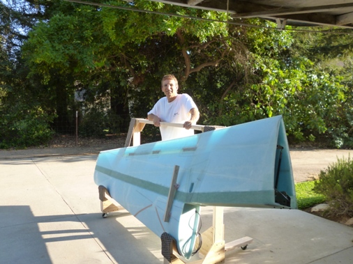
The plans say that this is "The Big One" and looking through the chapter it's pretty intimidating. Just look at all the boxes of foam I received. So I figure I'll just start with the easy stuff by cutting out the wing hot wire templates and the wing fixtures.
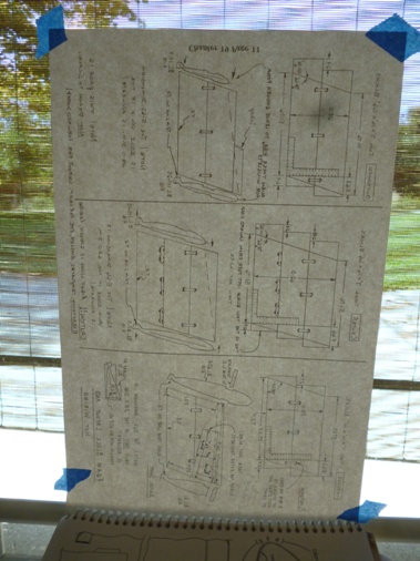
I asked Marc Zeitlin if he would come out to do a technical inspection of our progress so far. He is the foremost authority on the Cozy IV airplane and is a EAA Technical Counselor for this airplane design. He was more than willing to do the inspection and flew his Cozy from Tehachapi to Camarillo airport where I picked him up and then drove to my house. He was very complementary of our fiberglass work, his main critiques were that I used flox in places where micro would've been adequate and since flox is heavier it all adds up. Also for the hardware that bolts should have two to three threads showing beyond the nut. Much of the hardware I had was just for fitting purposes and will be replaced later with the proper length. While I was trying to absorb all the advice and knowledge that Marc was imparting, Lynn was writing it all down.
So here is a page of Marc's Inspection Notes.
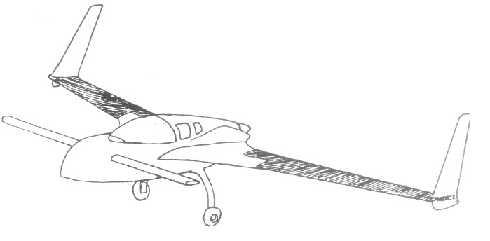
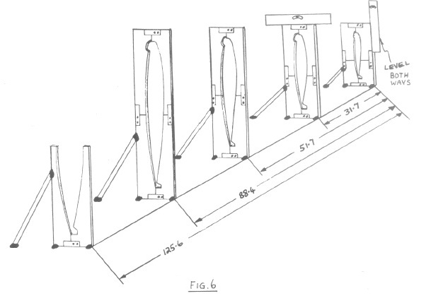
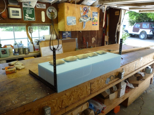
Here's a sketch from the plans that shows how the fixtures will be used to hold the foam core blocks in place when bonding them together.
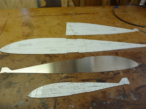
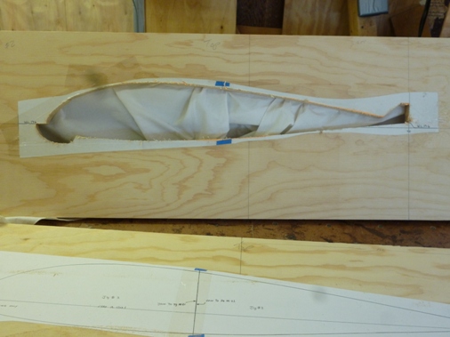
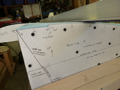
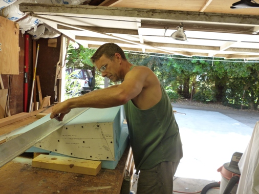
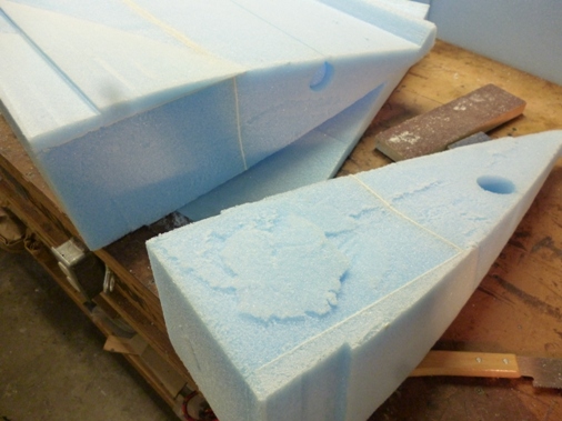
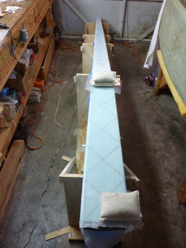
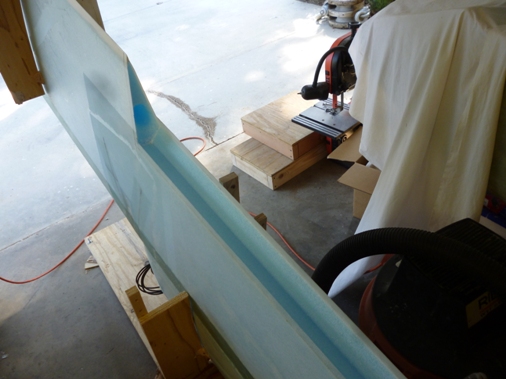
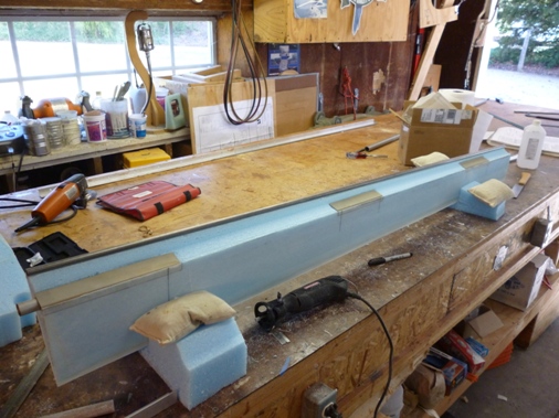
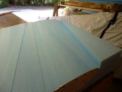
Based on Marc's suggestion I made hot wire templates 1/16" oversize for hotwiring and will then use the plans sized templates for spline sanding the foam cores to the correct size. So we hot wired the foam blocks using the 1/16" oversized templates. We also used inconel wire for the hot wire saw and it seems to cut much better with less lag leaving a uniform cut without a dip in the middle. I believe the inconel wire doesn't stretch as much when it gets hot. The plans have you hold the two foam blocks together with three popsicle sticks five minute epoxied to them. The placement of the sticks is more crucial than the plans would lead you to believe since in our first attempt the hot wire rode over the top of one of the popsicle sticks. Also the extra scrap of foam needed to accommodate the large B.L. 31 template needed to be much larger than what the plans called out. Once we corrected for these minor issues the cores came out very nicely.
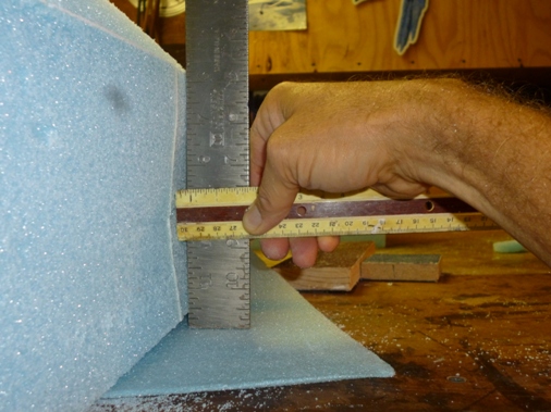
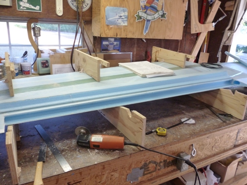
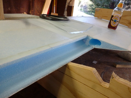
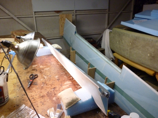
Here you can see sanding the extra 1/16" to plans size templates. The sanding board is a 2"x2"x6' aluminum "T" with 36 grit sandpaper glued to it. Also the spar cap trough is hot wired out.
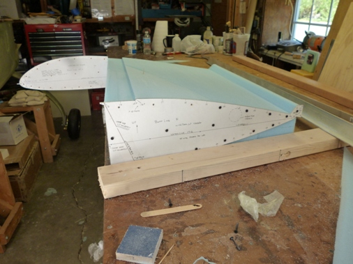
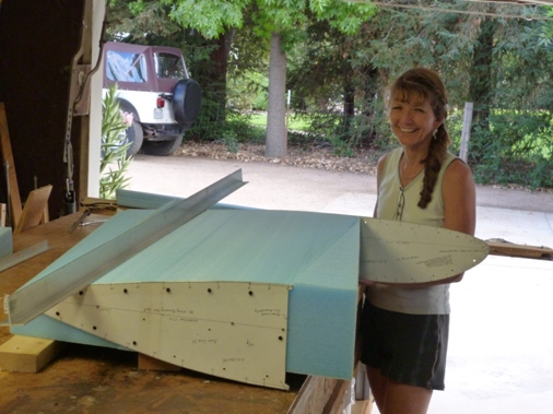
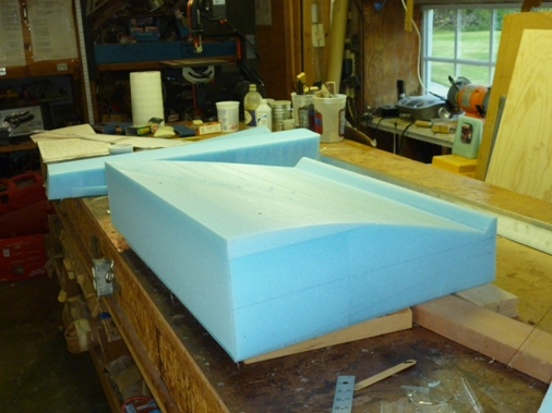
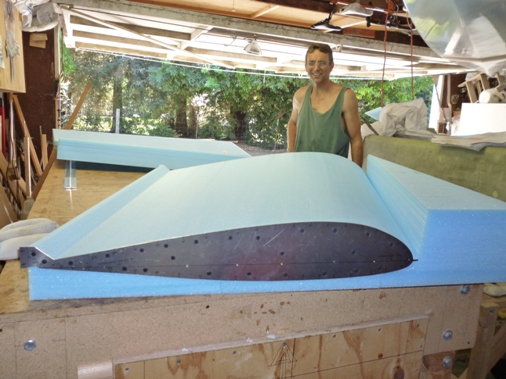
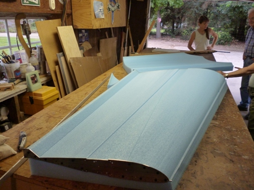
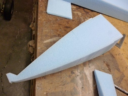
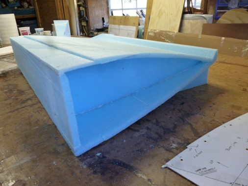
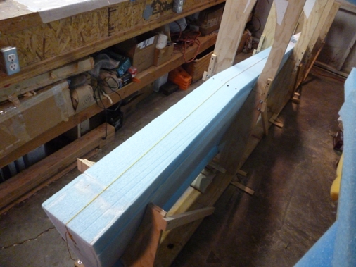
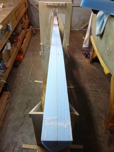
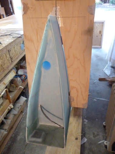
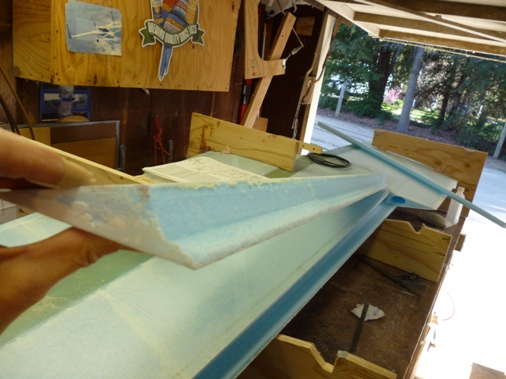
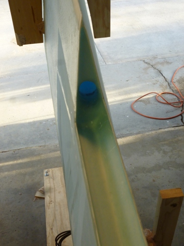
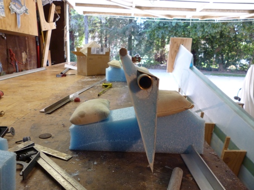
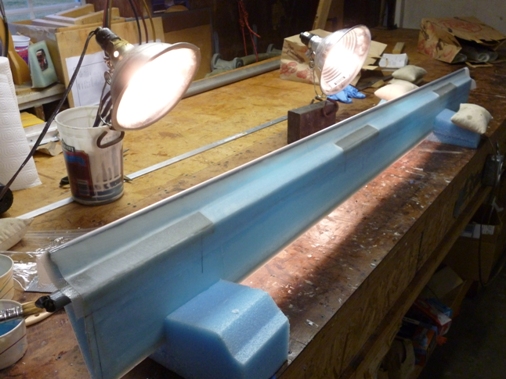
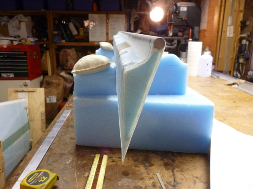
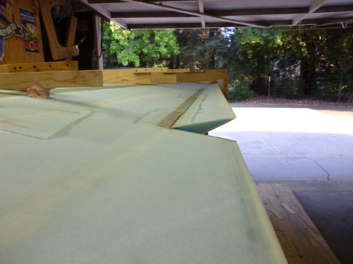
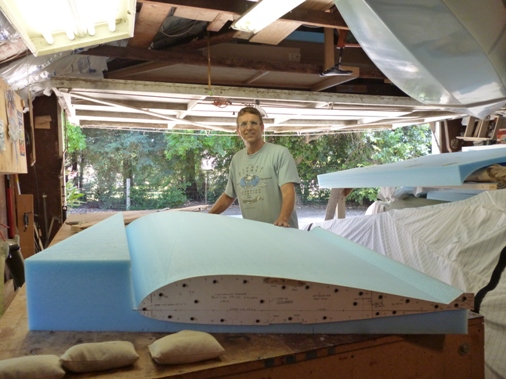
Here I'm doing some final touch up on the foam core. This inboard section doesn't have a leading edge since it is the wing attach point to the aft face of the center spar. The next picture is the wing center section after hot wiring, by the smile on my face you can tell it came out excellant, it's a shame to have to sand it down the 1/16" to the plans template. The inconel wire is the trick to making perfect hot wire cuts, there is virtually no lag to the wire if you get the tension as tight as possible and the temperature set for 1" cut every 4 seconds. I'm thinking for future cuts we'll go for broke and just hot wire the plans size templates.The wing center section is quite a bit bigger in span and chord (distance from leading edge to trailing edge) than the inboard section.
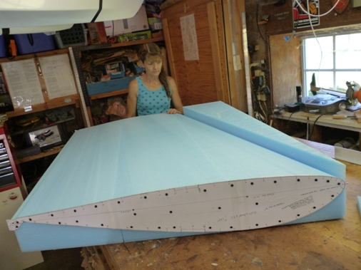
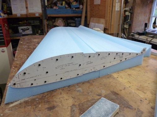
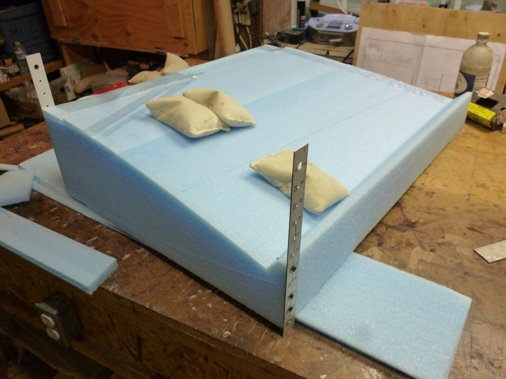
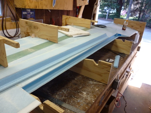
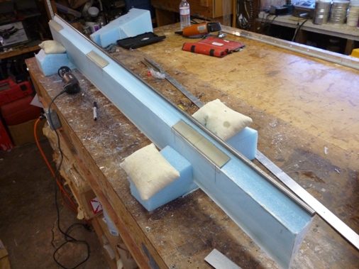
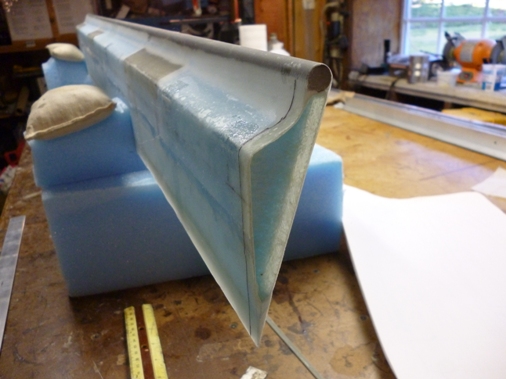
Lynn also marveling at the wonderful hot wire job. The second picture shows the core after sanding down the 1/16" and hot wiring out the spar cap trough. Similar to what was done for the canard.
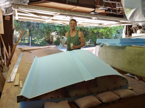
We hot wired the outboard section of the right wing and we did it to the final sized templates since we'd gotten so good at hot wiring. No need to hot wire oversize and sand down to size. There are three critical hot wire elements, use inconel wire, get the correct temperature and tighten the wire as much as possible. Tightening the wire is probably the most critical and with inconel it will ring when plucked when it's super tight. Also with inconel it doesn't stretch much when it gets hot.
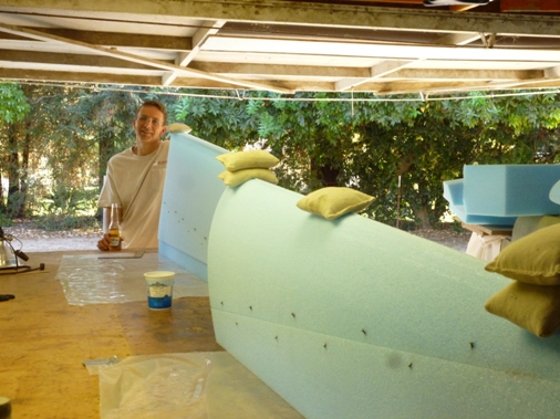
After hot wiring off the nose section at the forward edge of the spar cap trough we bonded the blocks back to together with micro so that each section (except for the inboard section which is one piece) would be in two pieces, the aft section including the spar cap trough. We kept the mirco a 1/4 inch from the edge so that it wouldn't squeeze out onto the wing skin surface and create bumps. The gap will be filled later with micro when the wings are skinned with fiberglass. It was hot this weekend, over a 100F, so a Corona was in order.
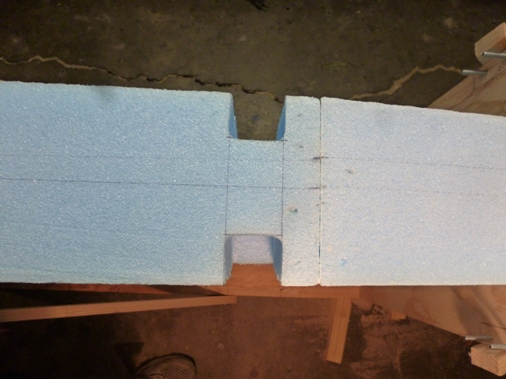
This weekend didn't go too well, the plans have you slice a wedge off the inboard wing section and then cut out the outer perimeter to create a cavity for the aileron control hardware; pushrods, bellcranks, etc. The plans say to cut the wedge off with a bandsaw, but if you don't have a bandsaw you can cut it with the hotwire as long as you haven't already bonded the blocks together. Well I have a bandsaw so I bonded the blocks, not realizing that it was too thick to fit in my bandsaw or even my bother-in-law's (Erik) much larger bandsaw. So future builders beware, you most likely will not have a bandsaw big enough. So I decided to carefully cut it with a razor back saw, the result which was much less than desireable. It wouldn't have been so bad but the inner surface ended up concave which is where hardware needs to mount to a flat surface otherwise I'd expect some binding of the aileron controls.
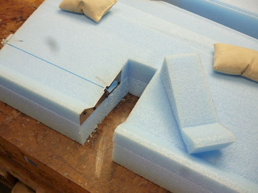
Since I bought some extra foam blocks for such an occasion we rehotwired the inboard section and before bonding anything hotwired off the 6"x1" wedge. Then I used Erik's bandsaw, mine was still too small for this operation, and cut the outer perimeter. This was also not the prettiest result as the cuts need to be vertical however it's not possible to place the one square surface face down since it will interfere with the bandsaw vertical part. I tried wedging one side up but in the end I just ended up eyeballing it. Luckily only one section is critical in getting the correct dimension which is where a wing mount will be, the rest can be off by a 1/4 inch.
So I ended up with something that was workable and bonded it back in place. Also made internal hotwire cuts for the eventual aileron cut out on the other outboard wing sections needed to cutout a block for the hotwire to fit in and then that will get bonded back in. The usual procedure make nice pretty airfoil wing sections, then hack them up and put them back together. Also made cutouts for the airleron torque tube and electrical wires, sorry no pictures of those.
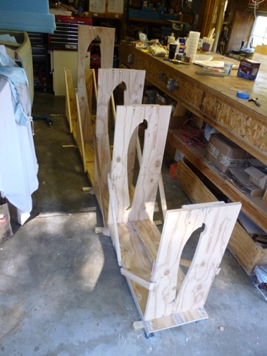
I completed the wing jig. I made a level base out of aluminum angle and plywood to set the wooden templates on. I screwed everything together instead of using bondo I also bolted the base to the floor using some super sticky hardware epoxy (PC7) to bond some lag bolts to the garage floor, the bondo was just not holding.
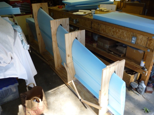
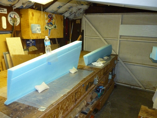
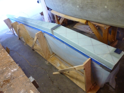
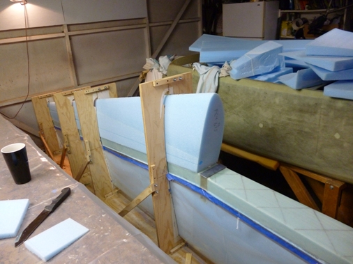
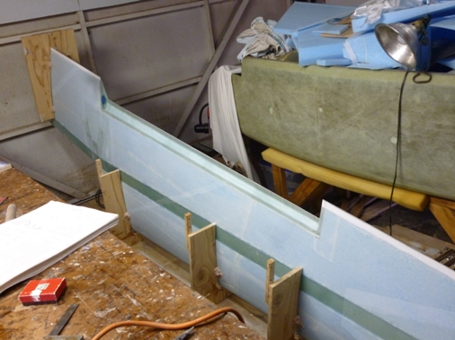
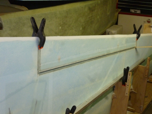
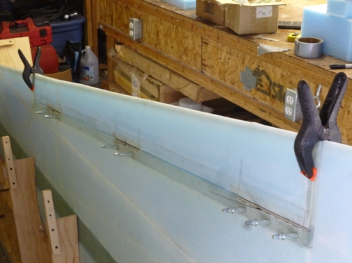
Here are the aft wing foam block sections microed together in the wing jig. I had to trim the wooden templates to get the foam to slide in and also had to shim the blocks to get tight micro joints. I used a string to make sure the wing was straight. What I neglected to do until after the mirco cured was to also check if the face of shear web was flat the entire length. There is a slight sweep back angle between the two outboard blocks that I can correct by adding a sliver of foam when attaching the leading edge after the shear web has been glassed.
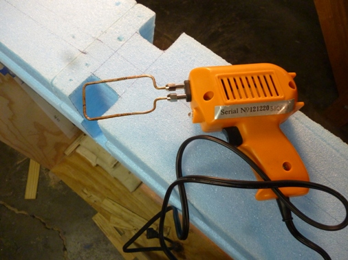
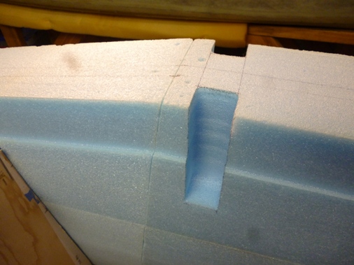
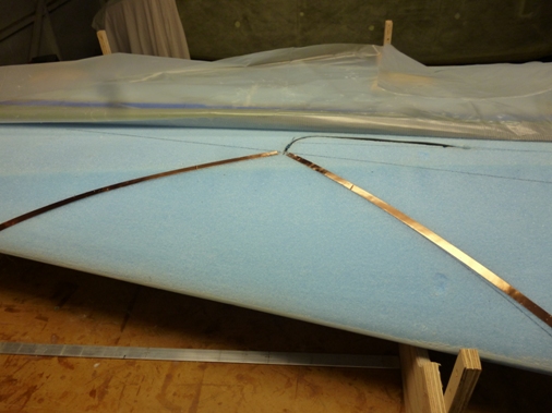
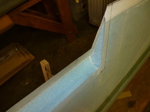
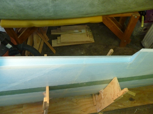
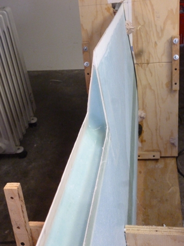
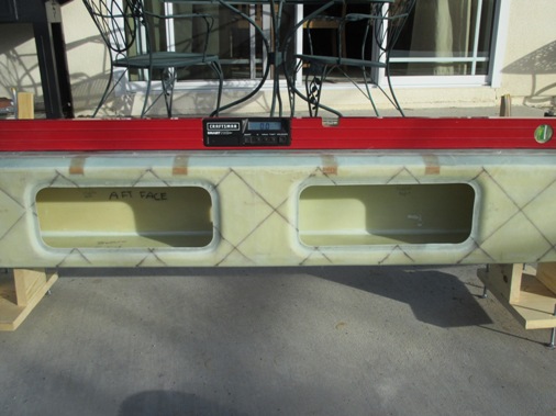
Here I hotwired the wing attachment access channels using my soldering iron. I bent some thick copper wire that fit in the soldering iron to the right shape and after a few practice attempts on some scrap foam I gathered up the nerve to perform the procedure on the wing foam. This worked out really well because now all the corners are rounded which will allow the two plies of BID to lay in nicely. There are some slight ripples that were quickly sanded smooth, probably too much coffee. To maintain the correct depth I marked two sets of lines on the copper wire, one set for cutting at the top and a second set for the step at the spar cap trough. I wetted out two plies of BID between two layers of plastic sheeting which in retrospect was probably not as easy as just laying in the raw cloth and then wetting it out. The plastic was too stiff to conform to the compound curves and was difficult to peel off the wet glass, I managed to make it work anyway.
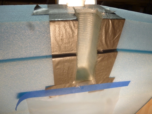
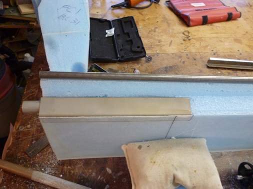
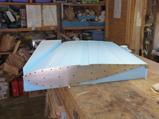
I microed in the LWA6 and LWA4 hardpoints flush with the foam as well as the W18 aluminum sheet metal pieces covering half of the access channel.
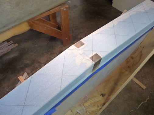
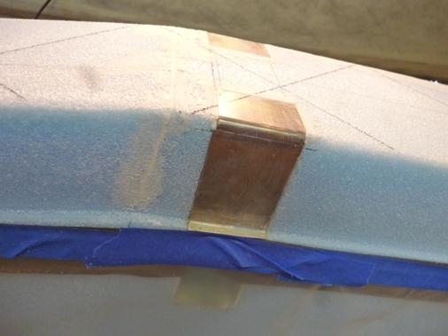
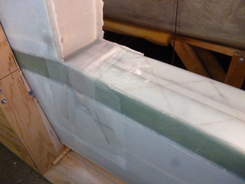
Here are pictures of the completed shear web layup which is 6 plies of UNI at a 45 degrees, alternating each ply. The first two plies are the full length the next two are about 2/3rds the length and the last 2 plies are a little more than a 1/3 of the length from the root. There are also two reinforcing layups over the hardpoints with 3 plies of BID with 1/8" thick aluminum plates LWA2 and LWA3 centered over those hardpoints. The 1/8" plates are weighted down with 10 pounds so I used some small brads (nails) to keep them from sliding out of position. This took us 5 hours to complete, seems like it shouldn't have taken so long and we were beat.
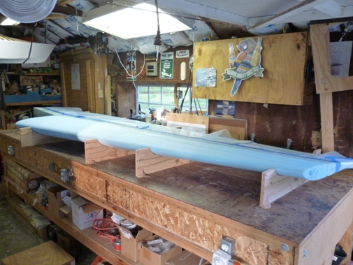
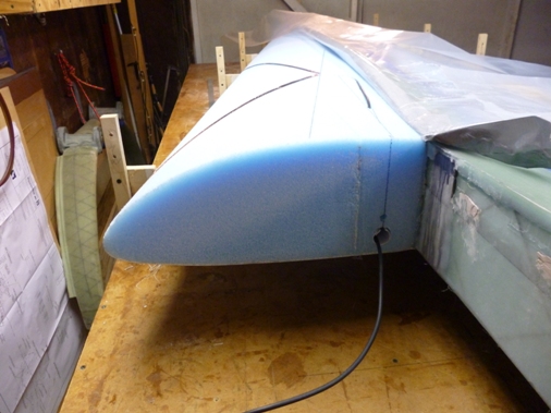
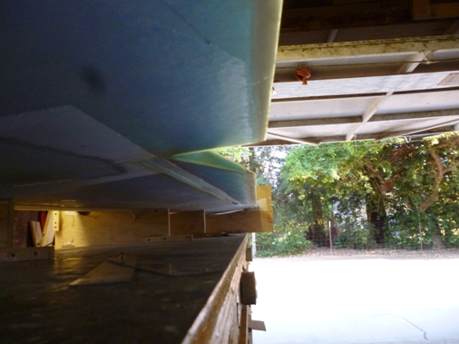
Here is a picture of the leading edge foam pieces bonded to the shear web, now it kinda looks like a wing.
Sunday December 9, 2012
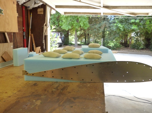
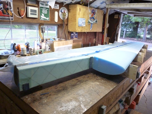
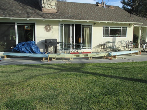
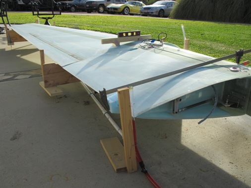
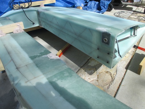
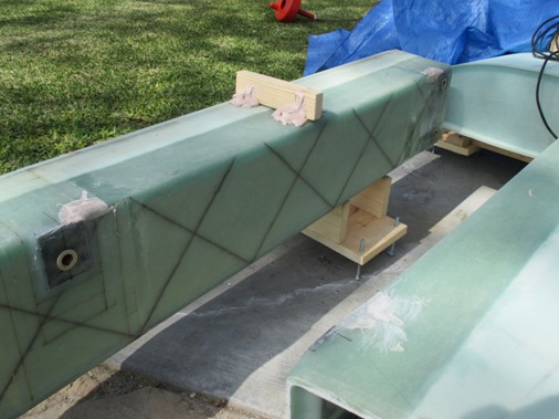
Got the wing up on the work table getting it ready to do the lower spar cap layup. The wing is sitting with the bottom side up. To keep the wing fixed in place it is floxed to the fixtures which will cause some nasty foam craters when it's released. The fixtures are also bondo'd to the table.
Sunday January 13, 2013
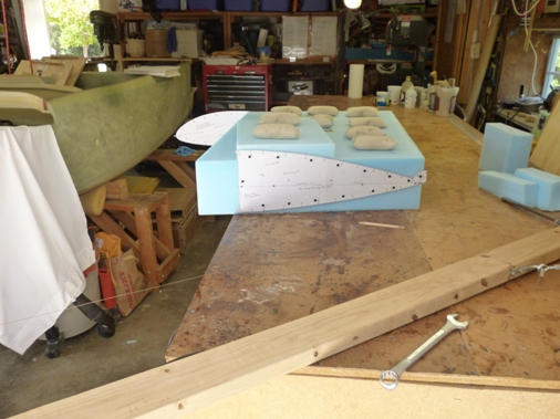
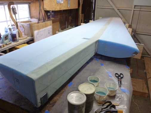
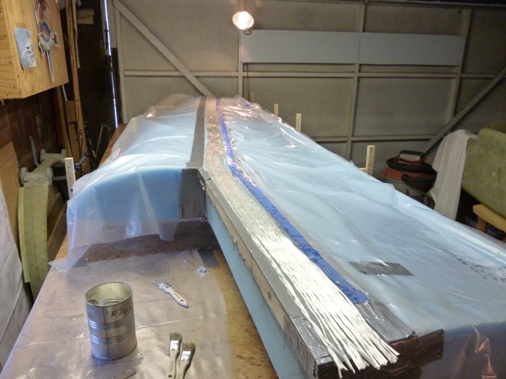
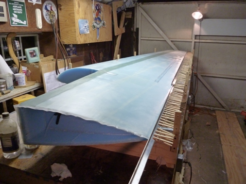
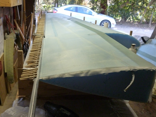
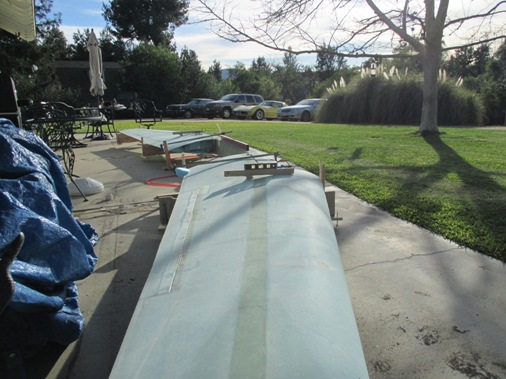
Another year gone buy and still working on the plane, but making some progress. Sanded the spar cap and foward face of the shear web and smoothed out the foam in preparation to skin the wing bottom side. The bottom gets two plies of UNI directional glass that is layed at an angle specified in the plans by spanning diagonally across the foam core joints, it's probably closer to 30 degrees as opposed to the typical 45 degrees. The plans allow you to leave the selvedge ends of the UNI glass on and just butt the glass next to each together, no overlapping here or else there will be a long linear bump in the glass.
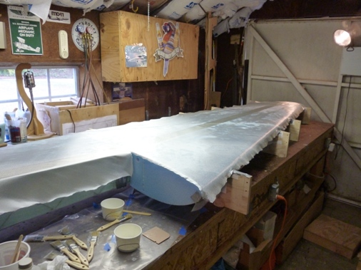
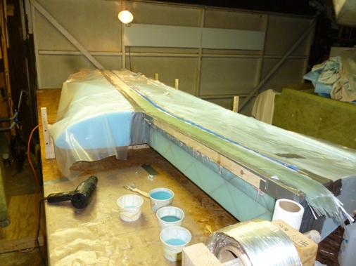
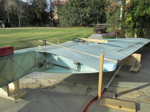
Here the second ply is layed on, alternating the direction. Forgot to take a picture after we were done doing the layup but here you can see the other halves of the fixtures installed in preparation to roll the wing over with the top side up. I was debating whether to peel ply the entire wing like I've been doing with everything else so far. Some builders claim that peel ply adds weight to the part and others say it doesn't. Since it's critical to make the aileron as light as possible for it to balance correctly I decided to just peel ply the areas called out in the plans.
Some fun with micro.
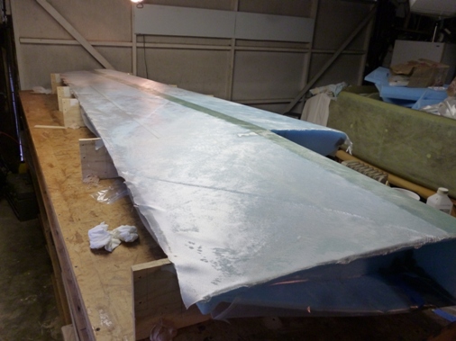
With the wing flipped over, top side up, we did the top sparcap lay-up. The top sparcap has a total of 12 plies, we managed to do this in 3 1/2 hours. We're getting faster.
Sunday February 10, 2013
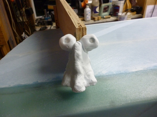
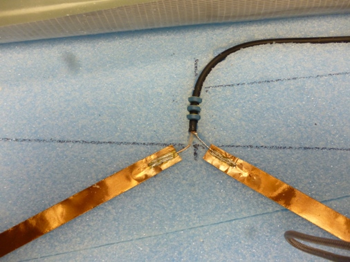
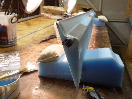
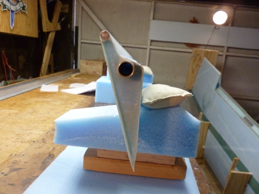
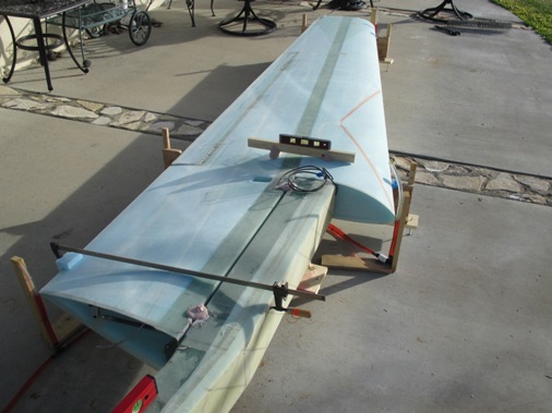
Here are some pictures of the navigation antenna installation, similar to the one installed on the canard. Kind of tricky to get the cable to exit through the electrical wire conduit. I heated up a 1/4 inch rod and melted through the foam and through my conduit liner, you can see one attempt came out a little high and too far inboard.
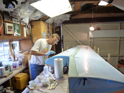
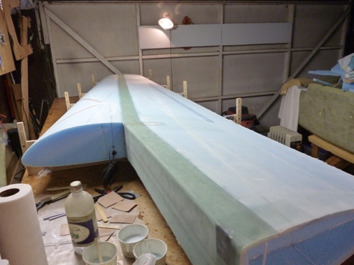
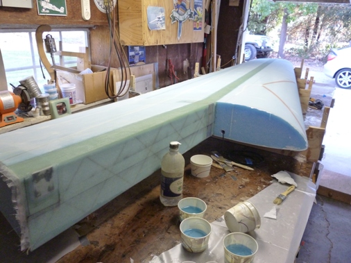
Finally had time to skin the top of the wing much like the bottom except for a thrid ply that runs from the wing root to the tip and forward of the aileron. Just doing all the micro filling and microing the entire wing took three hours. For some reason this took us a long time, from 11:30 am to 9:30 pm with an hour break to let the micro setup a bit. Part of the reason for the extra time was wrapping the glass around the leading edge. Also Lynn was sick but insisted on getting the wing skinned. Even though the trailing edge was pretty straight I followed what other builders had done and clothes pinned a straight edge to trailing edge to ensure flatness.
I was a going back and forth again about peel plying the entire wing and was about to pose the question to the Cozy email group when I found this email Marc Zeitlin's Suggestion on Peel Ply in the archives, wish I had read that before skinning the bottom. So we peel plied the entire top skin and I'll continue to do it this way, I think it will make finishing the surface much easier.
Sunday March 10, 2013
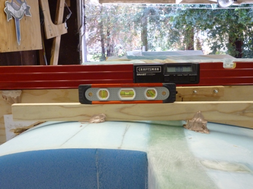
I bondoed on a piece of wood parallel to the wing waterline, this will be used to set the proper wing incidence (angle relative to the fuselage). Since the waterline is parallel to the top and bottom of the fixtures and I had leveled the fixtures to the table I just needed to level the piece of wood on to the wing. Next I glassed the nose rib with three plies of BID after routing out the foam 0.7 inches deep.
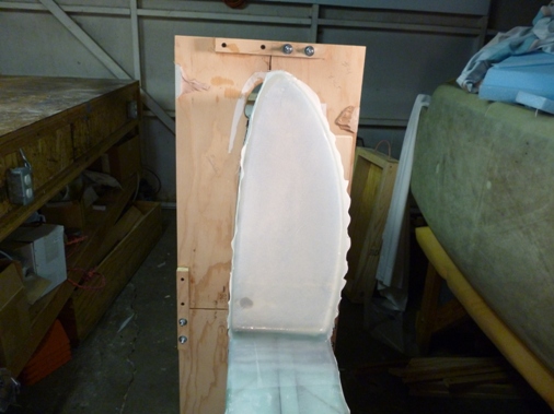
And also added the UNI buildups over the inboard wing mounts.
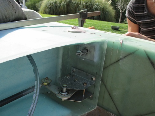
Next was glassing (3 plies BID) the aft inboard rib which also required some foam "surgery" to accommodate the aileron control rods and bell cranks. Surgery involved removing the foam 0.6 inches around the perimeter for a glass to glass bond and at the forward face but leaving the foam above the wing hard mount. Another 1/8 inch thick piece of aluminum is clamped over the inboard wing mounting point. After cure 1 ply of BID is layed up over the added aluminum square.
Finally the most dreaded task needed to be done and that was to cut the aileron control surface out of the wing. The measurements in the plans can be confusing since the dimensions are not where the cuts are made and the top cut is a different dimension from the bottom cut. I marked the lines on the wing and decided to do it slow and easy with a hacksaw blade by hand, drawing the teeth over the line an inch at time would be best. After about 5 minutes I decided that was too slow and pulled out my trusty Fein sander. With the Fein sander and a straight edge the cuts came out quite nicely. Afterwards a Newcastle beer steadied my nerves.
The angled surfaces on the aileron and internally in the wing were done with the hot wire when the foam cores were originally cut.
Sunday March 17, 2013
Now it was a matter of peeling off the 1" wide peel ply to expose the bare glass. To get if off cleanly I scored the foam at the peel ply line and sanded off as much foam as possible without sanding the peel ply. Once you sand peelply it's really hard to pull it off cleanly and you're stuck sanding it completely off. It was still difficult to peel off the peel ply so I used a chisel to help pry it up while simultaneously pulling it off. The foam was then blended into the glass.
I also recessed the ends a 1/2" per the plans, curving it a bit so the glass would conform nicely.
Three plies of BID at 45 degrees were layed up in this channel. We wetted out the glass first between plastic and then layed it into the channel, this works well for getting the fibers nicely oriented but has a better chance of trapping air bubbles. So you really need to inspect the lay up well to get all the bubbles out, but usually they'll be big and obvious. The ends were done as separate mini layups as well as the torque tube hole which needed to be glassed 1" deep. Also at the hinge locations an additional ply of Bid was applied.
Sunday March 24, 2013
Now the counter weight, torque tube and metal hard points for the hinges are installed on the aileron.
The counterweight is a 7/16" metal rod spanning the entire aileron and is microed to the bottom edge after slicing off 3/16" of the foam to leave a glass lip for the rod to bond to. I thought it would be really difficult to keep the rod in place while the micro cured but it actually behaved fairly well.
Here I dry fit the metal hard points for the hinges and the torque tube extending out an inch. The aluminum metal hard points are pre bent in an obtuse 60 degree "L" shape and the short 1/2" leg fits into a slot cut into the foam beneath the top skin. I had to open up the angle of the hard points for them to sit flush with the foam which caused them to not to be as flat as they were originally, hope that doesn't cause a problem. My metal working skills leave a lot to be desired, next time I will take more care in bending them, note to self.
Here are some pictures with the one ply of BID layed over the assembly. I made extra sure to round the corner at the top skin so there wouldn't be any problem for the glass to conform to it and it payed off.
It seems like one ply of glass is a bit stingy but that's all the plans call for and I don't want to do anything here that would upset the balance of the aileron.
Sunday March 31, 2013
Not much progress over the Easter Holiday but managed to recess the ends of the aileron by 0.4" and glass with two plies of BID. I also cut the hinges to length and notched the wing at the hinge locations.
Sunday April 7, 2013
Managed to get a little bit done this weekend. Got the hinges aligned and drilled holes through the wing and one hinge half for temporary instllation with clecoes (silver stud looking things sticking up from the wing). Timmed the aileron and the lower trailing edge of the wing so that the aileron would fit. This was necessary because the lower leading edge of the aileron became longer after installation of the counter weight rod. Used the hacksaw blade trick with some 5 minute epoxy/micro to stick the other half of the hinge to the aileron. A piece of hacksaw blade can be inserted through a hinge slot to push the other half of the hinge (with some dabs of 5 min epoxy/micro) up against the aileron. Now I can remove the clecoes holding the half of the hinge to the wing and remove the aileron from the wing and drill the holes through the hinge half epoxied to the aileron for pop rivets.
Sunday April 21, 2013
Now it's time to make the hinge attachment to the aileron permanent. I followed the plans rivet pattern and used clecoes to hold the hinge in place as I drilled subsequent holes.
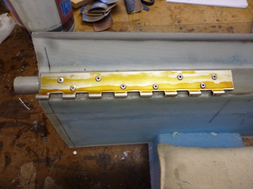
Here you can see half the hinge floxed and riveted in place. I was not able to keeping the flox out of the hinge holes and later cleaned them up with a 12" long 3/32 drill bit. The outboard hinge has some slight binding which I believe is because the metal plate imbedded into the aileron wasn't perfectly flat and when the hinge was pop riveted on the middle of the hinge pulled in slightly. After cleaning up the hinge holes and putting in the teflon sleeved hinge pin kit from Gary Hall (gary.chris@comcast.net) all the hinges move smoothly.
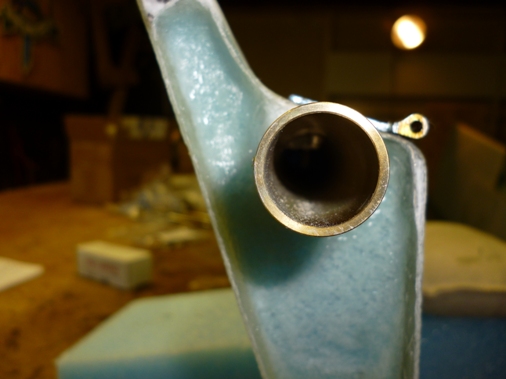
Here's a shot down the torque tube in an attempt to show how one row of rivets go all the way through the torque tube wall to solidly connect the hinge to the torque tube.
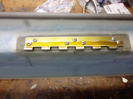
I decided to go the Click Bond method for attaching the hinges to the wing. This eliminates the screw heads that would otherwise protrude above the wing skin. The Click Bond head is only 1/16" thick so blending it into the wing surface shouldn't be too difficult. I also spot faced the wing skin area slightly, less than a 1/32", to help blend in the head.
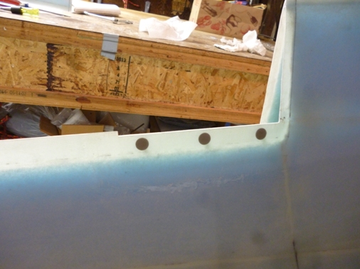
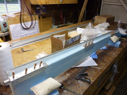
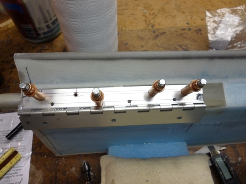
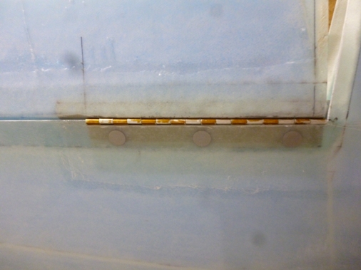
Here is a shot of the in-board hinge which is longer than the other two, so it has three Click Bonds floxed in place with one ply of BID over the top. Also shown is the back side of the hinge with some hardware store nuts holding the Click Bonds in place while the flox and BID cure, this will be replaced with aircraft quality self locking nuts during final assembly. I put packing tape on the underside of the wing and spread petroleum jelly on the hinge to make sure I didn't permanently flox the hinge in place. The funky gold and silver patterns on the hinge are the result of alodining.
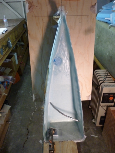
Now the moment of truth to check that the aileron balances correctly. I strung some safety wire across two wood up rights and through the two outer aileron hinges (per plans). The plans say that, "The aileron must hang between the angle that makes the top level and the angle that makes the bottom level, after painting." So it looks like without paint my aileron is within limits. If it's not within limits the plans allow you to sand partially through top ply of UNI on the top and bottom skins at the trailing edge, you're also able to add .3 Lbs to the leading edge. If none of that brings the aileron in balance you get to build another one, I'm not sure how you would ever do that. Lynn's pinky looks like it's lifting the trailing edge of the aileron but it's not. It was difficult to get a good picture.
So now we have smooth aileron movement up and down.
Sunday May 26, 2013
Now the linkage to actuate the aileron
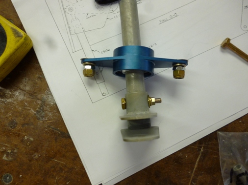
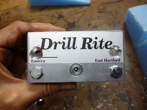
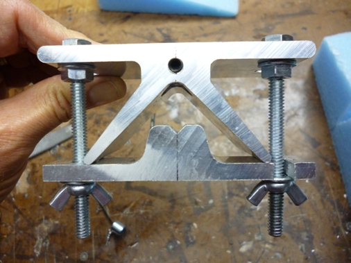
I'm using JD Neuman's spherical bearing for the support at the wing rib. I'm also using the Drill Rite drill guide for drilling holes in tubes. I had to modify it so that it would be able to grip on the torque tube extending out of the aileron and also drilling holes in the u-joint.

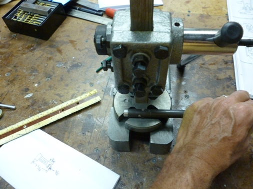
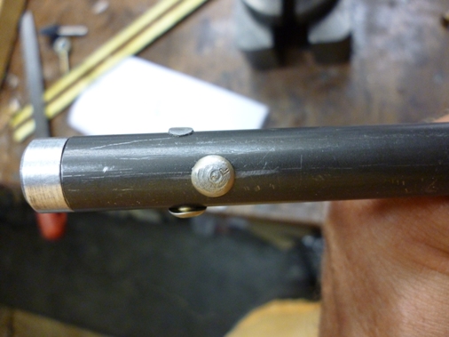
I thought I would try using an arbor press and a hammer to rivet the rod ends into the steel tubes. I drilled a dimple in the arbor press base the same shape as the rivet head. It worked but the result wasn't very good, the shop head wasn't the required 1.5 time the rivet diameter and the manufactured head was marred.
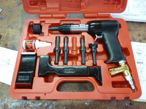
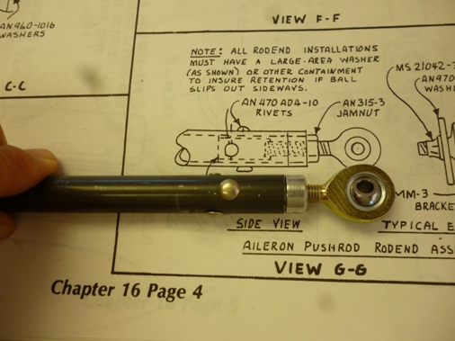
So I broke down and bought this rivet gun set from Aircraft Spruce for $200. I had done some riveting before when I got my A&P License but that was a life time ago so I was surprised that this kit had no instructions whatsoever. I was concerned about what pressure to set my compressor at, so I set it low and eventually settled on 60 psi. I did a trial rivet on a srap tube and the gun worked beautifully. So I riveted on the rod ends in minutes with no marks on the rivet head and the correct squish on the shop head. Sometimes it really pays to have the correct tool for the job. There will be a lot more riveting to do on this airplane so I think I'll get a good ROI on my $200.
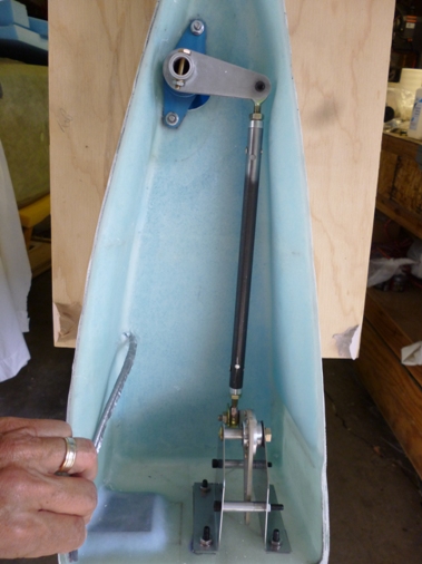
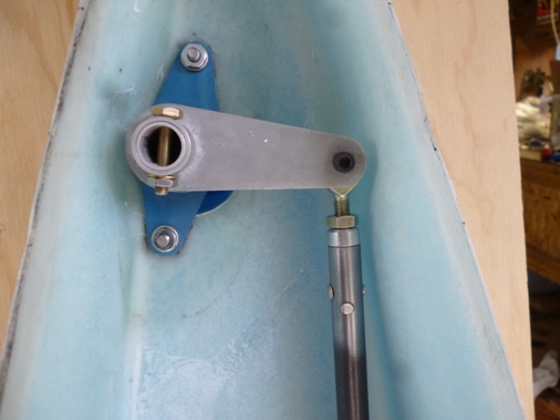
After a lot fitting and head scratching I installed the the control linkage. The bellcrank from CG Products has a hole for rigging the aileron in the trimmed position, which I used. I clamped the aileron trimmed with the wing trailing edge and drilled hoes in the torque tube so that CS132R arm (at the top) would be at 90 degrees with the CS129 push rod. However after everything was drilled and bolted up and I took the clamps off the aileron and because of the counter weight there was enough slop in the linkage to allow the aileron to droop from the trimmed position. So I adjusted the rod ends to get the aileron trimmed but now the CS132R arm is not at 90 degrees. I can still get the 20 degrees up and down range, more up than down so I'm debating if I should redrill the holes in the torque tube that goes through the wing. I probably will.
Sunday June 09, 2013
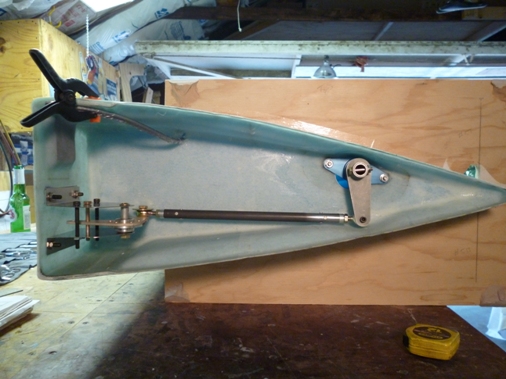
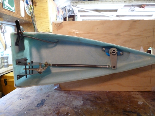
With the wing sitting on the table, here are before (left) and after pictures, after redrilling the holes in the torque tube in an effort to get the control arm more at 90 degrees. I got it a bit better but not perfect. I'm still able to get the 20 degrees up and down at the stops so I'll leave it as is for now. When I do all the controls later I may have to change it.
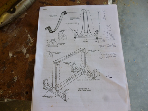
After surveying all the possible garage rafter locations I decided there wasn't enough real estate to hang the wing from the rafters. So I made a rolling wing cradel using Tony Bengellis' plans available from the EAA website. I modified the cradle for just one wing since that's all the width I have available in the garage.
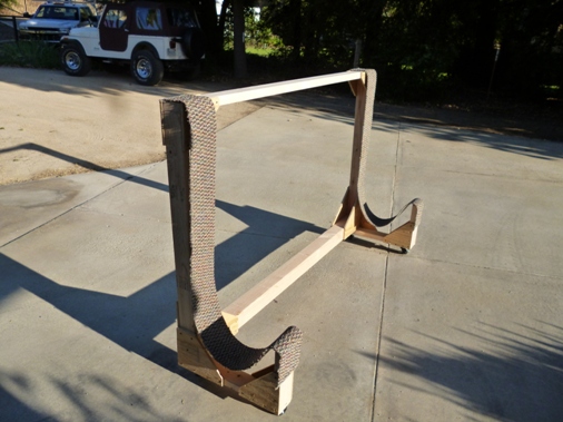
Here is the wing in the cradel. I added some foldable outriggers so it wouldn't blow over in case of a wind when it's rolled outside.
Thursday July 04, 2013
Just got back from the Canards West 2013 Flyin at Columbia Airport in Northern CA. It was good to see so many flying canards, over 20 showed up, VariEZ's, LongEZ's, Cozy's III & IV, a Berkut, and a Quickie. I will post pictures. Jay Skovbjerg gave a slideshow presentation on his flight to Alaska from Hollister, CA in his Cozy. Mike Melville gave a slideshow presentation on his around the world flight with Dick Rutan in LongEZ's. And Marc Zeitlin gave an eye opening presentation on unairworthy conditions he's seen doing annual and prepurchase inspections on carnards. It was great to talk with so many flyers and builders getting tips on how to do things.
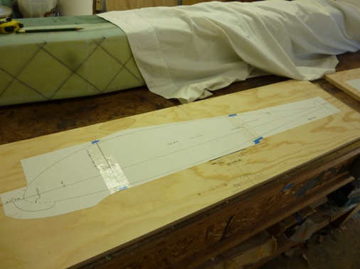
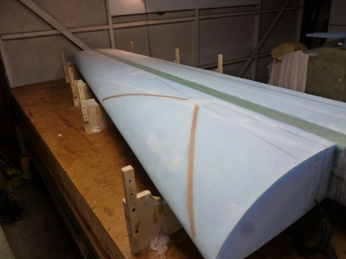
Upon arriving home it was a shock to see my airplane project with so much to do. So starting now with building the left wing. To make sure I wouldn't cut the foam again for a right wing I traced the back side of the wing foam layout page so it would represent the left wing and hotwired the foam blocks to the correct dimensions.
Here are some pictures of the hotwired center section. To have a beautifully curved shape in a matter of minutes is very satisfying!
Saturday Nov. 2, 2013
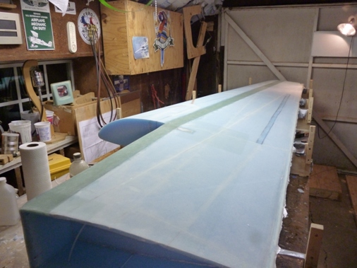
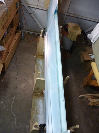
We're still working on the left wing. The foam cores are bonded together, the shear web is done, the top and bottom spar caps are done, the bottom is skinned and here's a pricture of the complete top skin. We were much faster this time the top skin only took 6.5 hours, last time it took 11 hours.
Saturday March 8, 2014
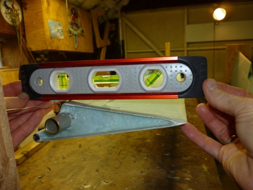
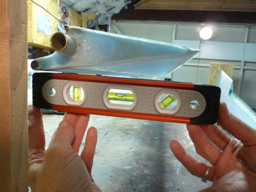
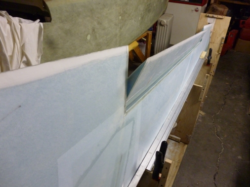
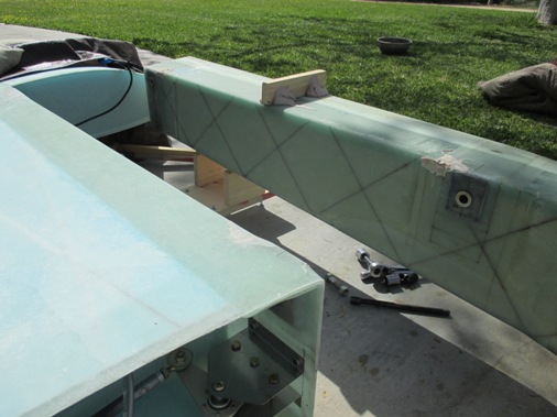
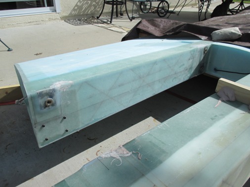
Finally getting around to updating the website. We finished the left wing so now was the task to drill the wing mounting holes while jigged to the center spar. I set up a number of water levels at the root and the tip and the leading edg and trailing edge of the wing per Wayne Hicks' website . This took a lot of trial and error to get everything level. For some reason to get the inboard sections of the wing to align with the center spar I needed to elevate the wing tips about a 1/2 inch from level giving slightly positive dihedral. The pictures tell the story.
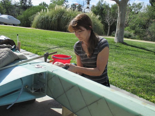
Lynn is drilling the holes because I was too nervous. Acutally it took about 20 minutes per hole to drill because the counterbore needed to be cooled with water frequently to keep from over heating the mounting pads, so I had two drills and two counterbores so we were both drilling away.
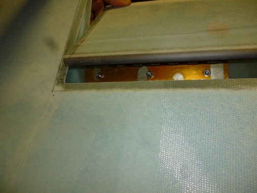
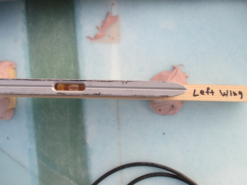
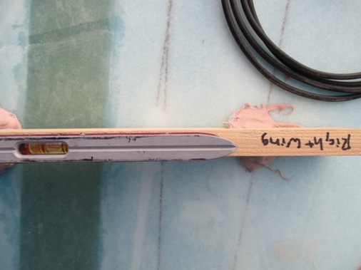
Here you can see the level boards for each wing. To get the wing mounting pads to be flush with the center spar mounting pads the wings leveled with the bubble within the lines but indicating slighly leading edge high relative to the level boards on the centerspar. So when I mount the center spar in the fuselage I will have the wings bolted to it to make sure the wings are level or slightly leading edge low.
Marc Zeitlin had a good email on setting the wing incidence, Marc On Wing Incidence.
So the last task with the wing mount holes is to flox the bushings in Place. I first did a dry fit with the bushings in the holes and everything bolted together. With the wings bolted to the ceterspar everything stayed level and in alignment. So the last step was to flox the bushings in and grease up the bolts and put it back together and hope you don't permanently bond the wing to the centerspar. It all worked out.
Now it's on to Chapter 20, the Winglets.