 Saturday, Feb 2, 2018
Saturday, Feb 2, 2018
Time to build the canopy frame which means attaching the turtleback to the fuselage which also means first attaching the center spar to the fuselage which was done in Chapter 14 Center Spar. This also means attaching the plexiglass canopy to the turtle back and creating a canopy frame around the plexiglass canopy to provide structure for hinges and latches. Note: I'm adding this to the website in Feb, 2019, a year later, so I apologize if the descriptions leave out some detail.
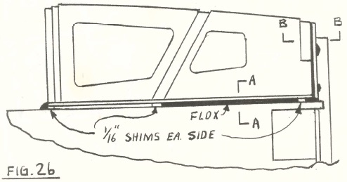
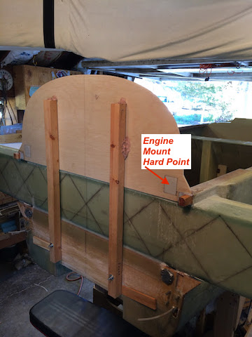
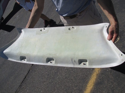
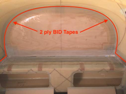
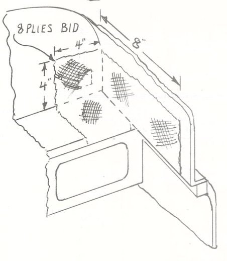
The first step is to install the upper firewall which was made years ago. I don't have a picture but the firewall was just slightly too small. There was an 1/8" gap between the firewall and the turtle back no matter how much I tried to stretch or shape the turtleback. I could have filled the gap with flox but decided instead to make a new firewall. The firewall is made up of an expensive piece of plywood and a ply of BID on each side with two aluminum hard points installed for the engine mount. I made the hard points larger this time to allow for engine mount tolerances. Two wood uprights bolted to the lower firewall hold the upper firewall in place with bondo. As shown in Fig-27 there are several 2 ply BID layups to glass the firewall to the center spar. A plywood firewall doesn't sound like it would offer much protection but there will also be a layer of insulation called Fiberax and then a sheet of stainless steel over that.
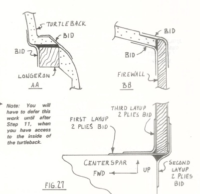
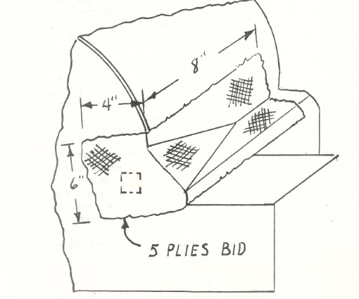
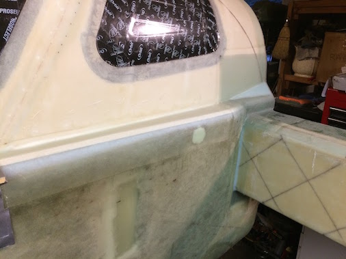
The turtleback was glassed to the firewall and the longerons of the fuselage (only from the canopy cutline aft to the firewall) with flox and 2 plies of BID. A foam fillet was microed into the corner and 5 plies of BID was wrapped around the corner overlapping onto the engine mount insert.
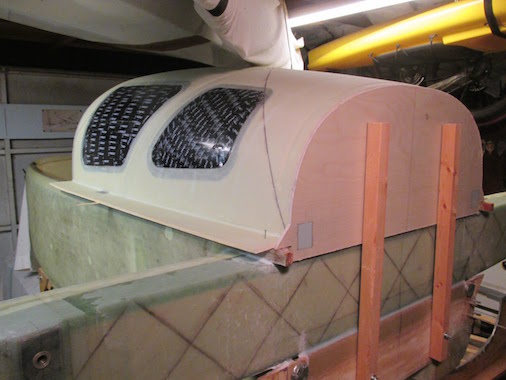
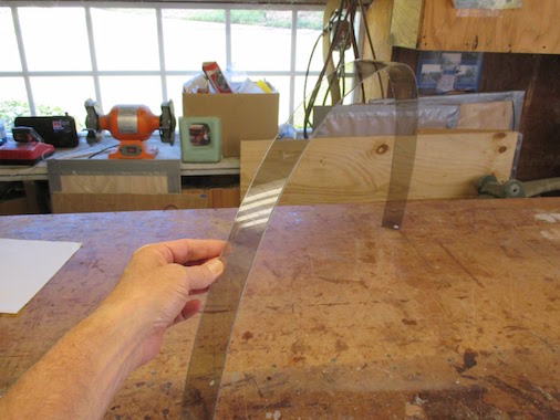
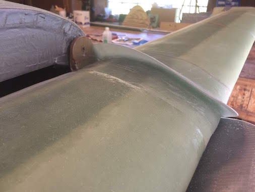
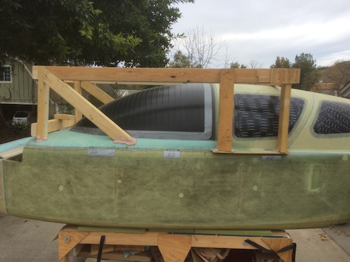
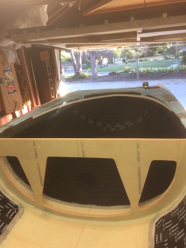
With the turtleback glassed in place there was no way to avoid having to work with the plexiglass canopy. It amazed me how flexible it is, it is very noodley, it will widen and become shorter or narrower and taller. With some blocks screwed down on the bench I could control the width and then determine the height to see how it would match up with the turtleback. Also to determine at what location the canopy slope leveled out.
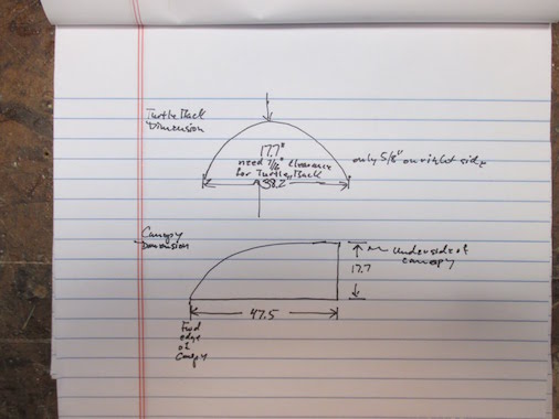
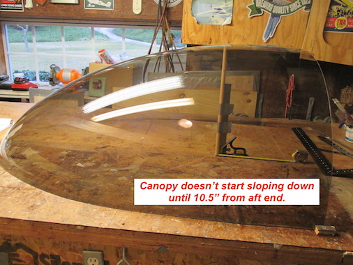
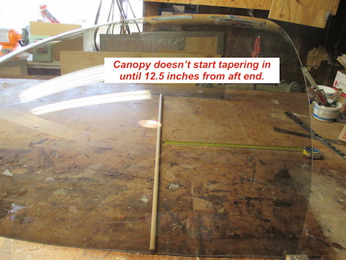
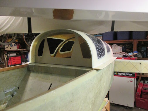
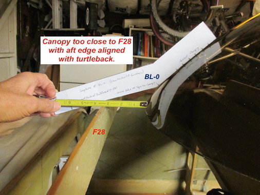
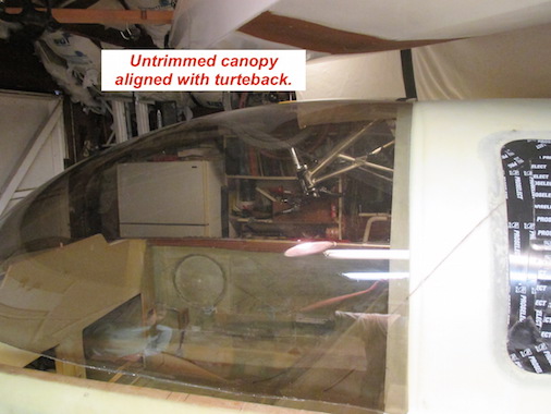
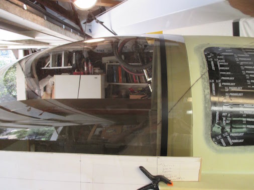
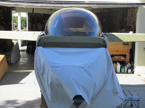
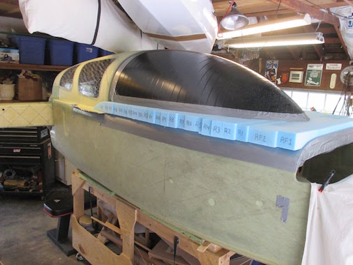
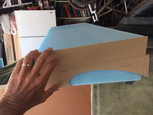
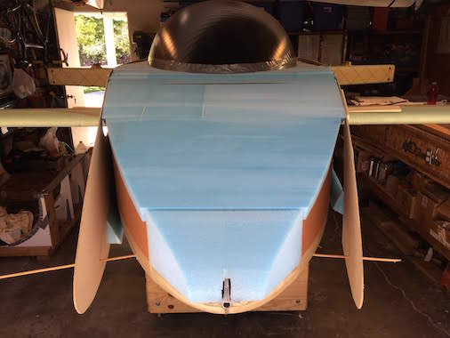
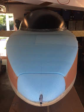
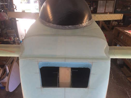
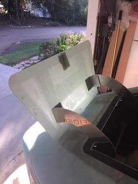
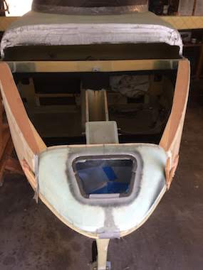
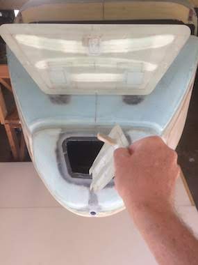
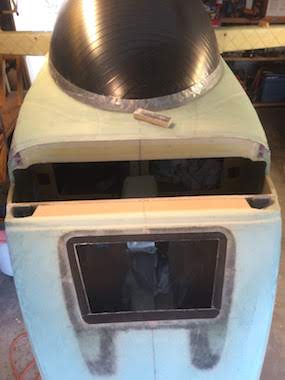
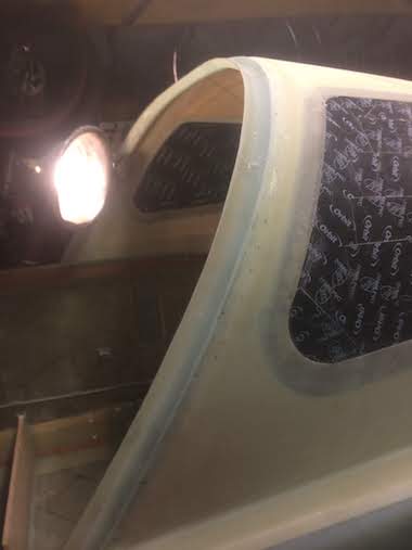
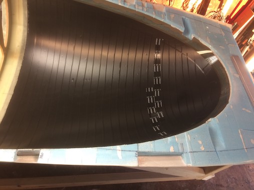
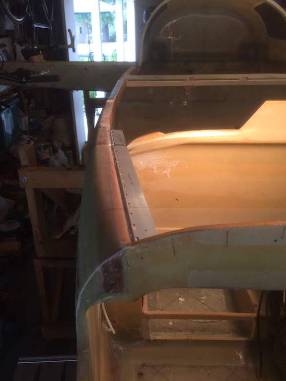
I did a lot of measuring, checking and fussing with the canopy to come to the conclusion that it was too big, even though I had increased the width and height of the turtleback. This is one of Tod's Texas Canopies so it is made larger than the standard canopy. The canopy needed to be trimmed at the aft edge so that template B.L.0 would position the nose of the canopy at the correct distance and angle from bulkhead F28. This first picture shows that the canopy is too far forward necessitating trimming the aft edge.
The group provided a lot of input regarding trimming the canopy and leaving a gap at the bottom edge, the discussion can be found here, Cozy Group Canopy Discussion.
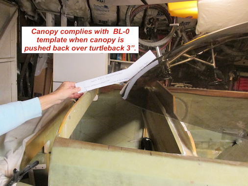
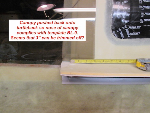
With Tod's Texas canopy and a 1.75" wider and taller turtleback I trimmed 2.25 inches off the aft edge and .25 to .50 inches off the bottom edge. To mark an accurate line on the canopy I applied electrical tape to the turtleback where the aft edge of the canopy needed to be then with the canopy in place applied tape lining up the tape edge with the tape on the turtleback. I used the Fein sander to trim the canopy, making very light impressions going over the same line, 20/30 times until the cut was all the way through. It was very nerve racking not to slip and scratch the plexiglass.
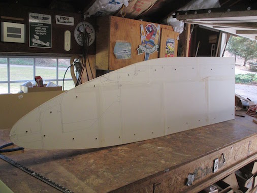
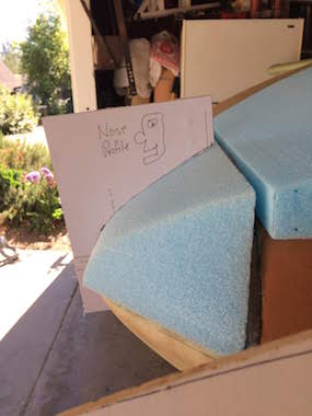
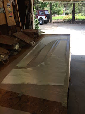
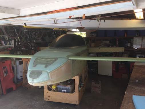
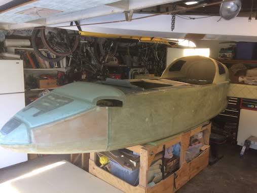
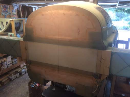
I made full size side profile templates from hardboard so that the canopy frame would flow nicely into the top of the nose, this is why the nose section has been left unfinished for so long. The plans have you finish the nose section much earlier which many builders find it difficult to shape the canopy frame into the nose. Lynn and I will hot wire the top edge of the canopy frame forward of the plexiglass all the way down to the nose using these hardboard templates.
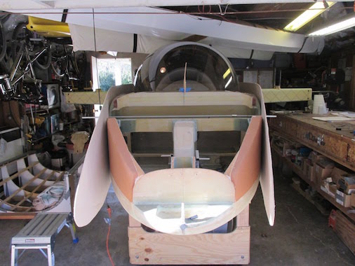
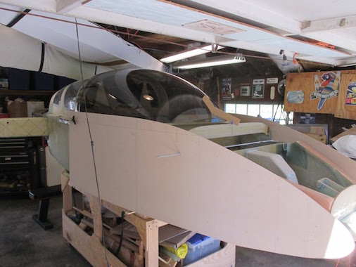
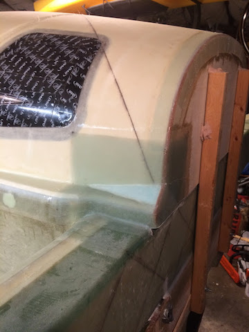
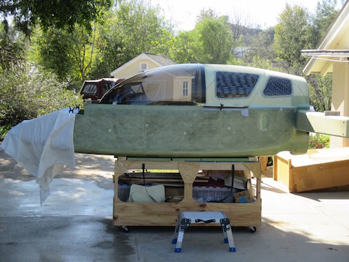
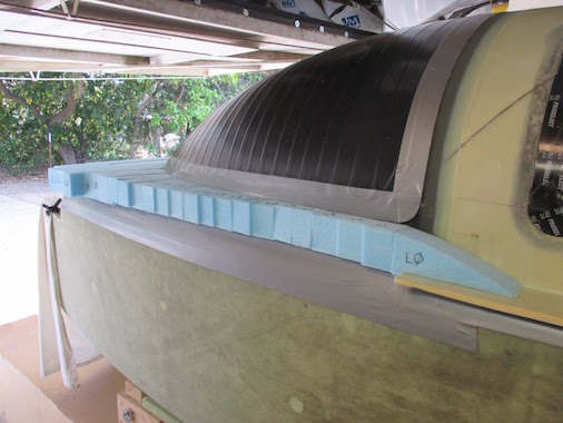
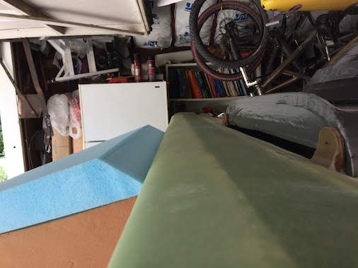
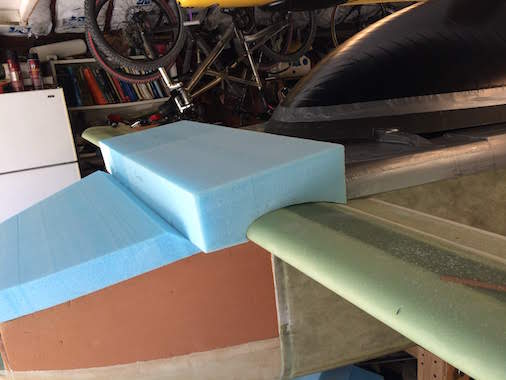
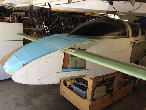
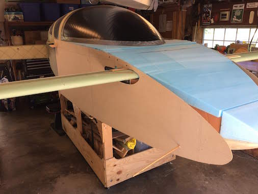
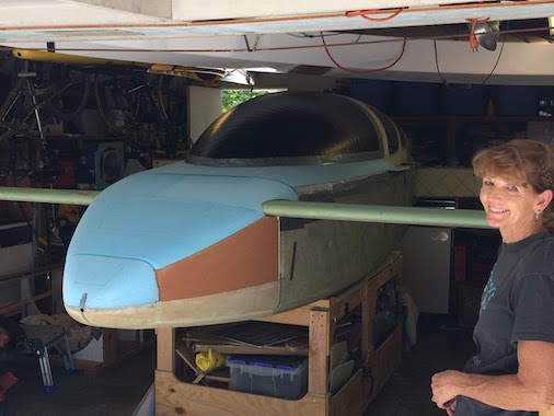
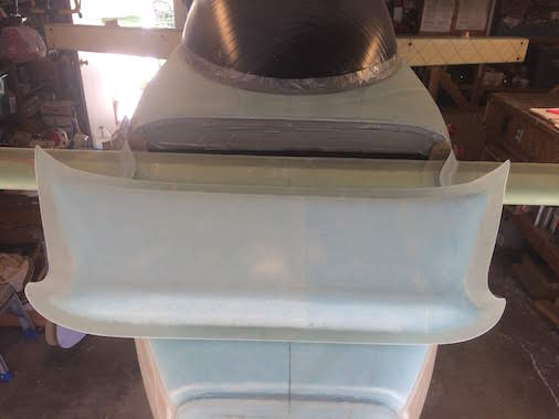
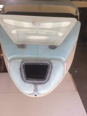
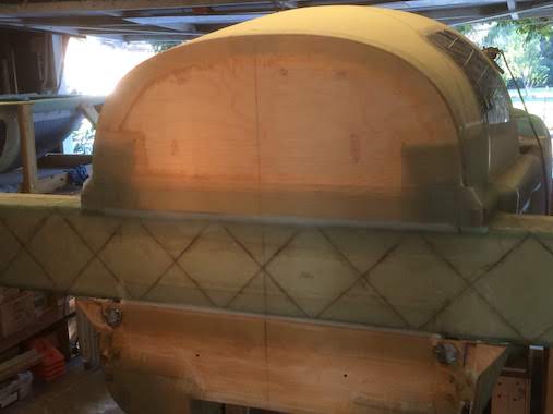
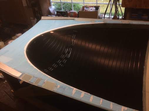
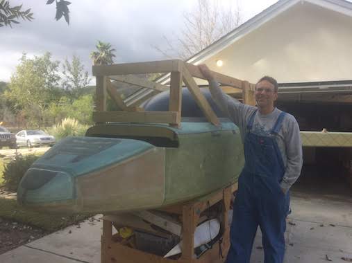
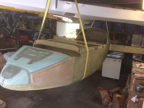
I pulled the fuselage outside so I could stand back and take a good look at how the plexiglass canopy fit with the turtle back and get an idea of the overall flow. It looks a bit stubby but I'm hoping that the canopy frame and nose section will help smooth things out, we'll see.
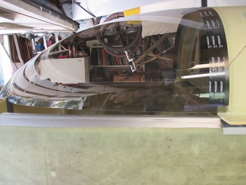
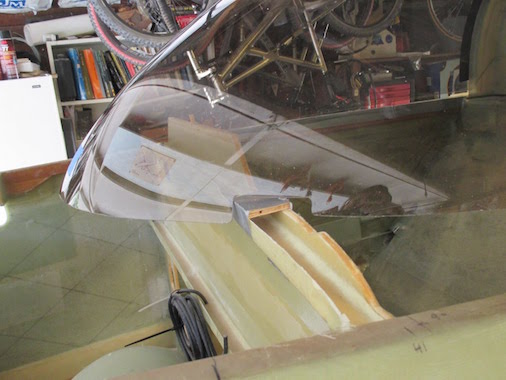
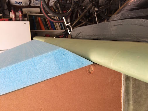
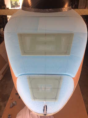
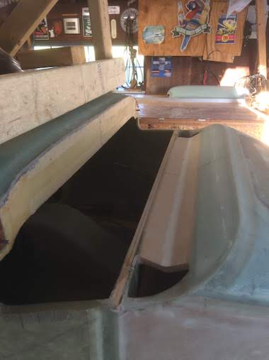
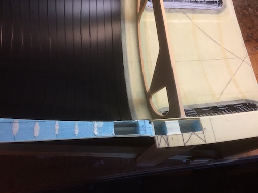
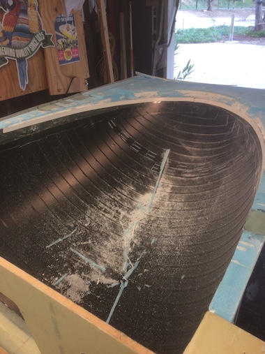
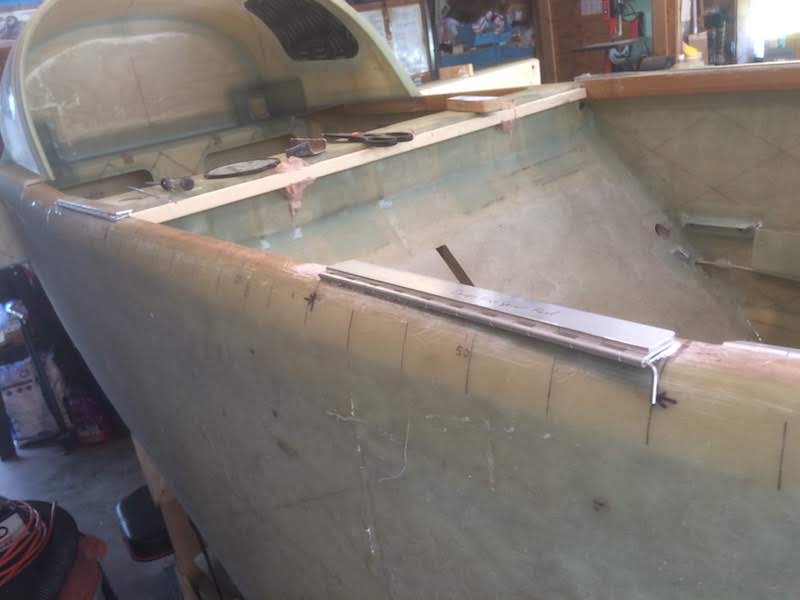
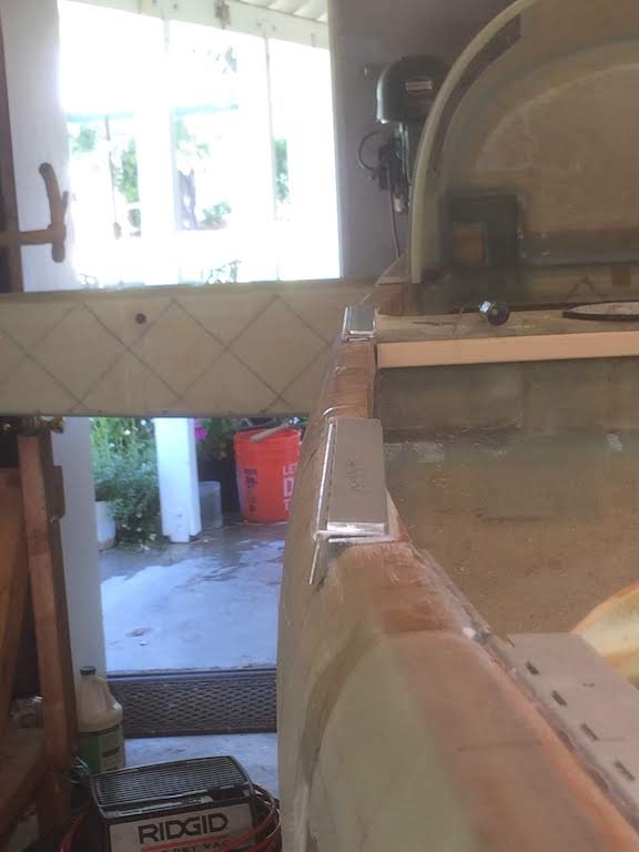
This shows the bottom edge of the plexiglass canopy trimmed with a minimum 1/4 inch gap to the fuselage. I taped a 3/8" piece of foam on top of the longerons to allow a gap for a seal between the canopy frame and fuselage. In the Cozy Group Canopy Discussion Marc Zeitlin highly recommended doing that. Also a notch is cut at the forward end to allow clearance for the instrument panel.
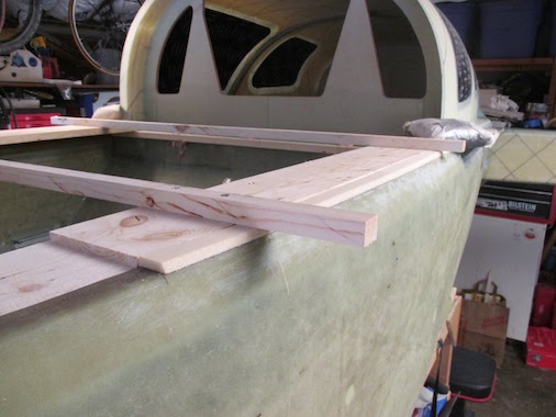
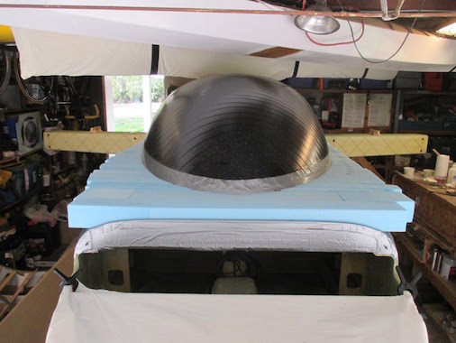
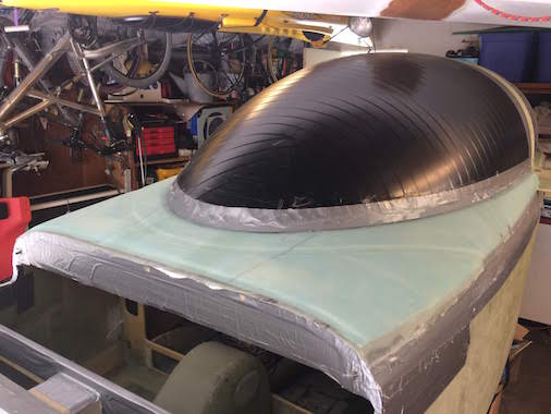
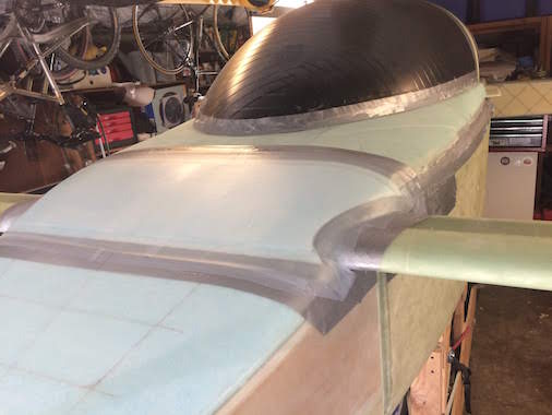
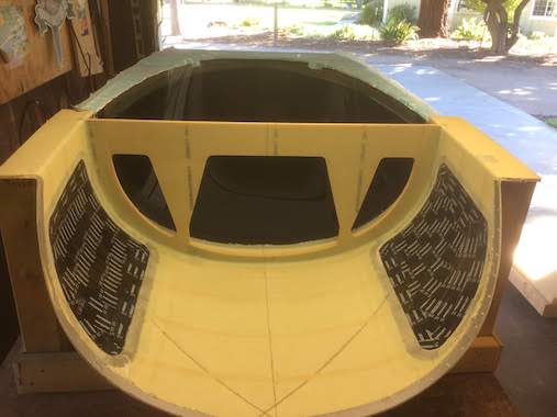
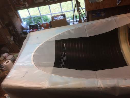
Before glassing the plexiglass canopy to the turtle back some temporary support structure is put in place to allow a surface upon which to build the canopy frame. This will provide a platform for the canopy frame foam.
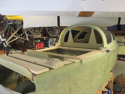
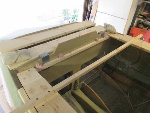
The support structure and everything else possible is covered in duct tape. Also the plexiglass canopy is covered in 2" wide plastic plumber's tape, I opted for this instead of the Spraylat, both options were offered in the plans. Seemed to me that the tape provided better protection and some builders complained that if the Spraylat was left on for a long time it can be very difficult to get off. Others said that you just need to apply several coats to to make it thick and it's no problem. Considering how slow a builder I am I went for the tape.
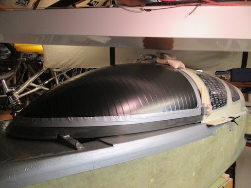
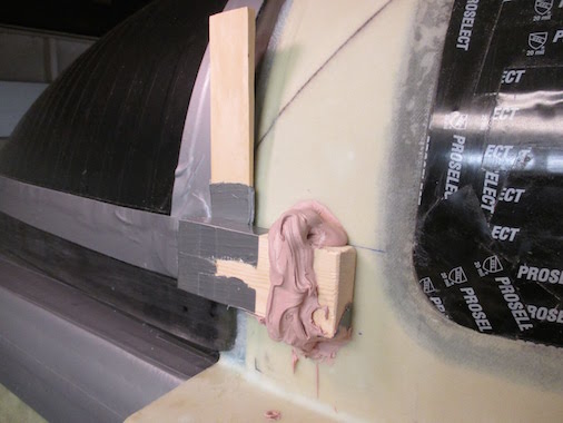
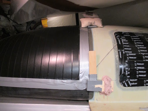
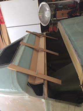
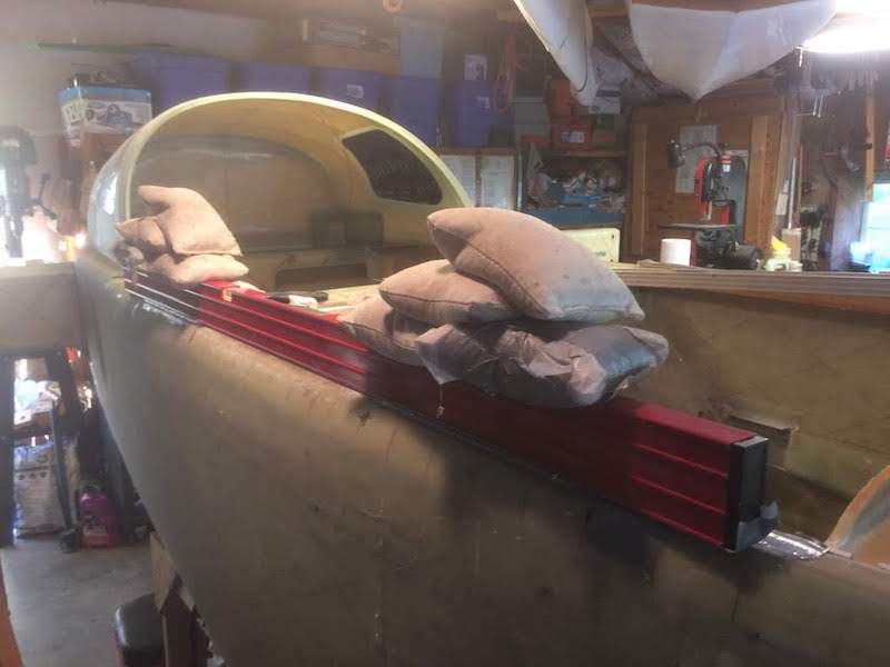
Next is to flox the aft edge of the plexiglass canopy to the forward edge of the turtleback. The challenge here is to get the plexiglass canopy to conform to the shape of the turtle back, it wants to pop out at the sides and the top which the plans say will happen. Per the plans I bondo'd a board to each side so I could wedge the canopy to the turtleback and weighed down the top. With that it worked really well for a good bond.
After the flox bond of the plexiglass canopy to the turtleback cured a Ply of UNI is layed up at the bottom edge of the plexiglass canopy and overlapped onto the turtleback. Once that is cured 3 plies of BID is layed up over the plexiglass canopy to turtleback joint. (Sorry, don't seem to have pictures of that.)
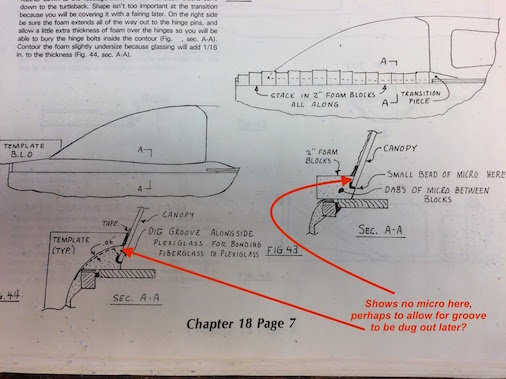
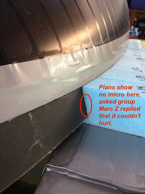
I had some concern that the plans didn't show applying micro between the canopy frame foam and the bottom edge of the plexiglass canopy where the single ply of UNI is. The group said it would be fine to apply micro just not up to the top edge of the foam since that is dug out to create a groove where flox and BID will be layed up to create a hard edge between the canopy frame and the plexiglass.
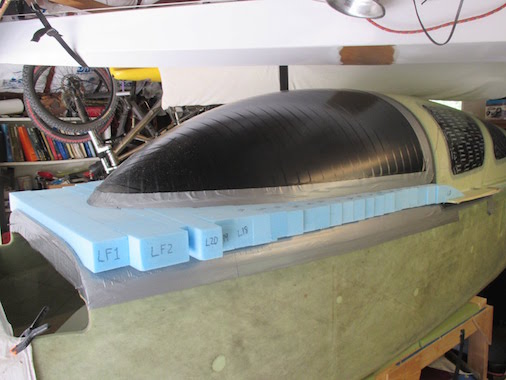
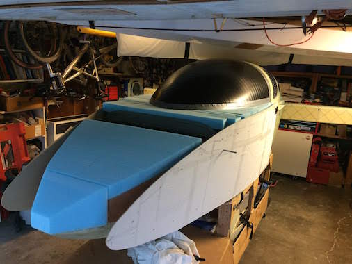
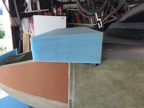
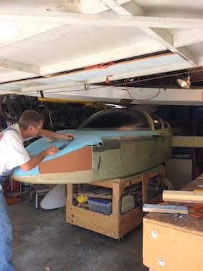
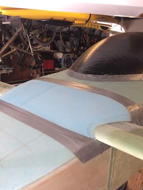
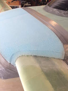
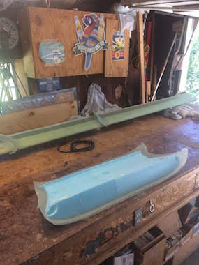
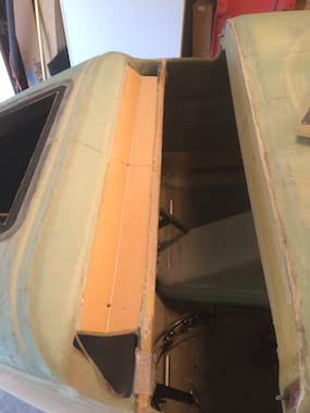
The foam that comprises the canopy frame is made up of 2 inch wide pieces with a lip that fits under the plexiglas canopy. It was a bit challenging to make them but after a while you get the hang of it, using an angle finder you're able to mark the angles of the plexiglass since it's constantly changing. At the forward edge of the plexiglass canopy I couldn't shape a piece that would have a close enough fit so I made a template to hot wire the foam and micro'd a 1/4" of foam to the bottom to create a lip. It still took a couple templates to get the shape right.
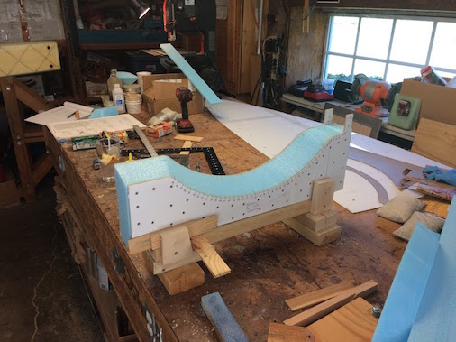
Before rounding the corners I wanted to get the top profile established with the side templates. I microed some blocks of foam together to fill in the nose section.
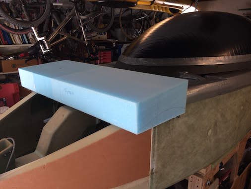
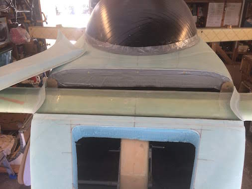
The piece of foam that covers the canard was a little bit of a challenge to ensure that it sat at the correct height. So I created an inverse template from the original canard template to create a void for the foam to sit on top of the canard locating it accurately.
With all the foam blocks in place we could hot wire the top profile using the side templates. I hot glued some dowels to hold the templates out at the front otherwise the slope would not be correct.
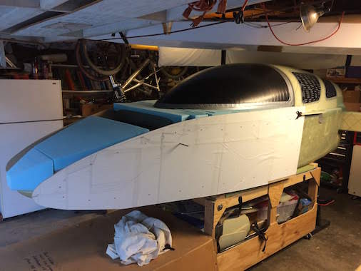
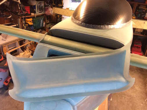
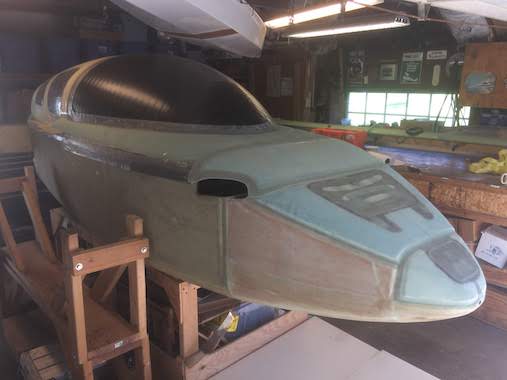
I then shaped the corners trying to keep everything looking symetrical. I think the nose may look more blunt than other Cozy's or LongEZ's I've seen. But at some point you just have to call it good and move on.
It seems to be a pleasing shape which is the typical requirement called out in the plans.
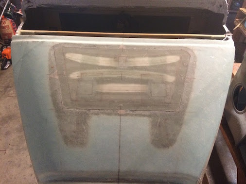
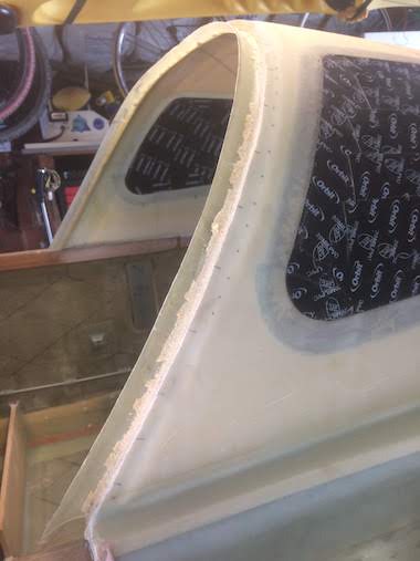
8Before glassing the nose the access doors are glassed over the foam to get the exact curvature of the nose. So I marked the foam where the access doors would be and then covered the area with packing tape and layed up 4 plies of BID over the marked areas. After the access doors cured they were removed (along with the packing tape) to be used later. Now the entire nose area could finally be glassed with 2 plies of BID.
9
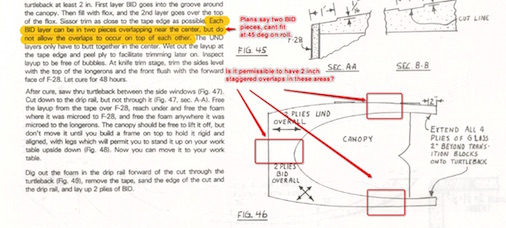
Now the canopy frame could be glassed. I was a little concerned that the plans didn't mention allowing to overlap the plies of BID along the sides, I queried the group and the consensus was that it was fine as long as the overlaps were not in the same place causing a bump. It didn't seem possible to me to layout the pattern for one side of the canopy at a 45 degree angle on a roll of BID.
I hogged out the foam to create a groove at the base of the plexiglass, a 1/2" wide and deep. The first ply of BID is layed into the groove and then the groove is filled with flox and the second ply of BID is layed up over that to create a hard lip around the plexiglass canopy. 2 plies of UNI go over that for a total of 4 plies of glass on the outside of the canopy frame. Shaping the canopy frame foam was a bit challenging, again to maintain symmetry between both sides.
10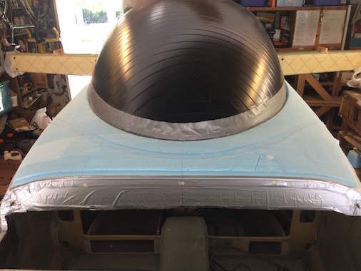
A curved recessed channel is sanded around the forward section of the canopy frame where it will be cut later. The recessed channel allows for a lip to cover the cut line.
11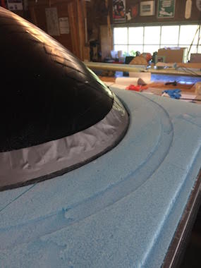
The canopy frame is glassed with the two plies of BID, with a BID/flox sandwich at the base of the plexiglass canopy and 2 plies of UNI over that. It always feels good to finally have the fragile foam covered with glass to make it solid. The pictures make it look pretty smooth but when you run your hand over the glass it has hills and valleys. Hopefully I'll be good in the finishing stage to smooth this all out. When shaping the foam it's hard to smooth it out perfectly because you can only sand the foam away to smooth it out to the point where you've suddenly created a flat spot that doesn't look quite right or symmetrical with the other side. So it is what it is and you have to move on.
12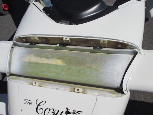
I had seen on Marc Zeitlin's site that he had made several improvement modifications to his plane, one of which was to have a removable canard cover. The reason for having a removal canard cover is to be able to have access to the screws that hold the "fuselage top" (the area forward of the canopy frame cut line) on. The fuselage top is removable to gain access to the area behind the instrument panel, generally where all the avionics equipment is. The plans have you bond (micro) the foam on to the canard and shape the foam and glass it, so the shaped area above the canard is permanently attached. Therefore you have to remove the canard to remove the "fuselage top" to access the avionics equipment. It seemed to me that it would be nice to have easy access to the wiring and avionics equipment, probably where most of your troubleshooting will be. So I decided to make the canard cover removable like Marc's. Here is how he described it on his website Marc Zeitlin's Improvement Mods scroll down to "New Removable Canard Cover". I was especially amazed how he made the complex curved flange on the canard that the cover attaches to. During the 2018 Columbia Flyin I talked to Marc about his removable canard cover and he took the time to explain how he did it and actually removed the cover to show how it was attached to the canard and fuselage. Builders are constantly seeking his advice and he is always generous with his time and knowledge, he is truly amazing! The pictures above show his removable canard cover, those are the actual hands of Marc Zeitlin!
13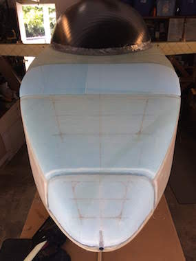
So the secret to making that fancy flange is to sand an impression into the canard cover foam for the thickness of the flange and then put duct tape in the recess and layup BID into the recessed area and overlapping on to the canard 2 inches. I ended up with 4 plies of BID to fill the recessed area. This comprises the external part of the flange.
14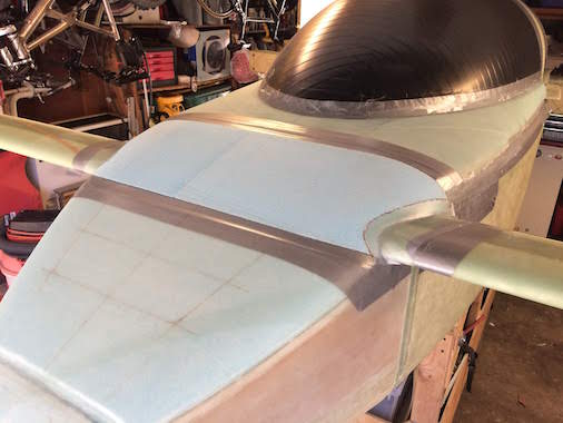
After the external part of the flange is cured, it is covered with duct tape and I cut the foam along the perimeter of the flange as deep as possible so the it would be possible to remove the canard cover after it was glassed. The entire canard cover was glassed with 2 plies of BID including the duct taped area covering the flange.
15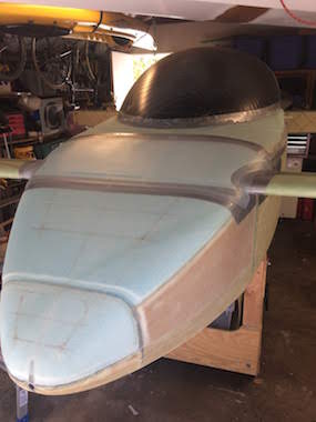
After the canard cover is cured you very carefully pry it from all the duct taped areas. It really does not want to let go, I find a narrow paint scraper works best to gently pry the glass from the duct tape and a lot of patience. You can see in the upper right photo the canard cover removed from the canard after glassing. The foam on the underside is shaped to a concave curvature leaving a thickness of 1 inch wherever possible.
16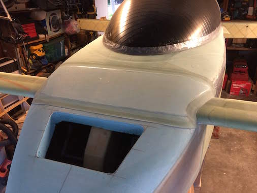
I glassed the underside with 2 plies of Bid and added 2 ply strips of BID to the edges for extra thickness and strength for the attachment points. As you can see I also cut the opening for the access door. I used the Fein sander to cut the straight sections and a rotor zip bit for the rounded corners. I could then use a rounded Perma Grit sanding tool to finish the corners.
17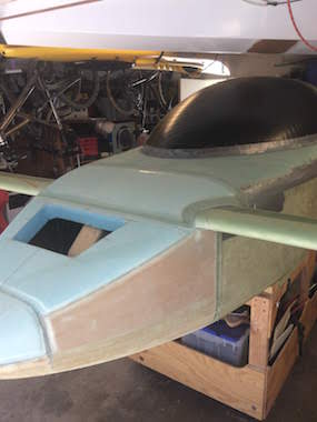
I love those shapely canard cover attach flanges. After the top of the canard cover was glassed and removed I could remove the foam on the interior side of the flange and added 4 plies of BID with a flox corner on the inside of the flange, so the flange has a total of 8 plies of BID.
18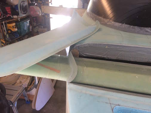
More close ups of the flange after the 4 plies of BID were applied to the interior side.
19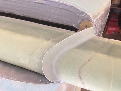
20
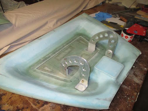
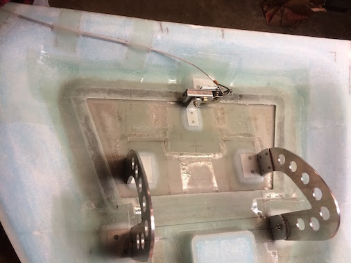
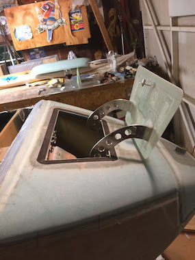
Okay enough admiration of the canard cover and flanges. So now it was time to shape the underside of the nose section and glass that. Of course I couldn't follow the plans configuration for the access door, which is to have a removable door with screws to hold it on. At the 2018 Columbia Flyin I met Rick Hall who had a very elegant access door using "J" hinges and a latch with a cable release making opening and closing the access door quick and convenient. He explained to me the details of how he did it and I took several pictures but of course once you actually start trying to implement many more questions arise and Rick was very responsive to my emails. He even made me two different sized striker cylinders on his lathe. So in the picture the underside of the nose section foam is shaped and sanded down to the top side glass to allow flat areas for the J-hinge attach points. The square shaped foam is where it attaches to the forward part of the NG-30 side panels and nose gear box. At the bottom you can see a thick aluminum plate and nut which is where the nose gear pivots for extension/retraction. I layed up 2 plies of BID on a flat surface and after cure floxed it to the square opening at the top of the nose gear box. I made a channel of flox in the top of the panels that make up the square box and then put the cured 2 ply BID sheet on top. This wasn't in the plans but I thought this would give a solid surface for the squared surface on the underside of the nose section to bond to.
21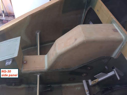
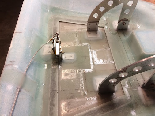
Here you can see that I've trimmed the nose door to fit the opening in the nose section and bondo'd in place to be flush with the upper surface. I don't have any pictures of glassing the underside but I wanted to have a foam rubber seal for the door so I bought 1/16 inch thick foam rubber that is 7/8 inch wide and applied that to the permitter of the door and then applied duct tape over that so that I could glass a lip to the underside of the nose section for the door to close against. So the entire underside of the nose section was glassed with 2 plies of BID then the permitter of the opening was glassed with an additional to plies of glass as well as the area where the J-hinges would attach. Here you can see some cardboard mock-ups of the J-hinges. I had first made a full scale side profile moveable model on paper to prove out the shape of the J hinge. Lynn's Dad, Erik also came up with some shapes that helped me determine the final shape. I though I could determine it with different radius circles but eventually with the full scale paper model I knew where the door attach points needed to be in the open and closed positions and then could arrive at a shape.
22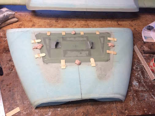
I cut the J-hinges from 1/8 inch thick 2024-T3 aluminum sheet. I used 5 minute epoxy to position the angle brackets and J-hinges to the door to establish the position and ensure the door opened and closed correctly. I marked the positions and used a heat gun to release the 5 minute epoxy and then floxed the angle brackets to the door and nose section.
23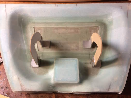
I cut lightening holes in the J-hinges with a hole saw.
24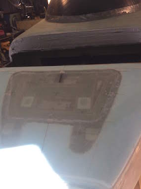
25
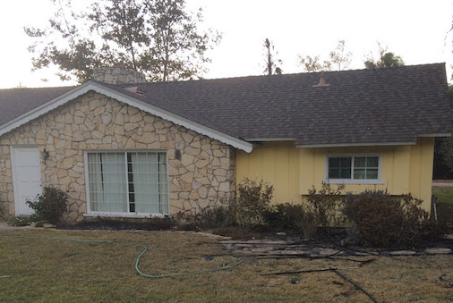
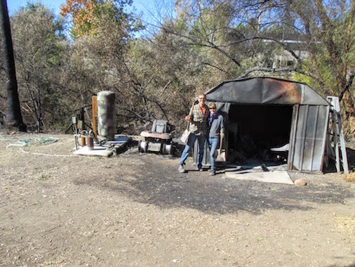
Then the Woolsey fire came through our backyard and singed the front living room window a bit. We were extremely lucky, when we evacuated the trees on our property were going up in flames and we were pretty sure that our house and everything would be gone, including the airplane. When the steel shed went up in flames it caught Firefighters attention that happened to be patrolling the area and they put out the fires and saved our house, garage (with airplane inside) and all our cars. After we evacuated I was convinced the airplane burnt up in the garage and couldn't even think of starting over, I'd probably buy a flying Cozy or partially built one, but luckily I still have mine. Fires come through our area about every 3 to 5 years (but seldom through our property), so I may need to come up with a plan to evacuate the airplane. When we finally decided to evacuate we first stopped in an Albertson's (grocery store) parking lot to be sure we wanted to leave the area, because once we left we would not be able to get back in, what was strange was that the parking lot was filled with cars but there was absolutely nobody around, it felt like the Twilight Zone. What we realized was, everybody who had evacuated left their extra cars in the parking lot since it was probably safer than at their home, another fire lesson learned.
26
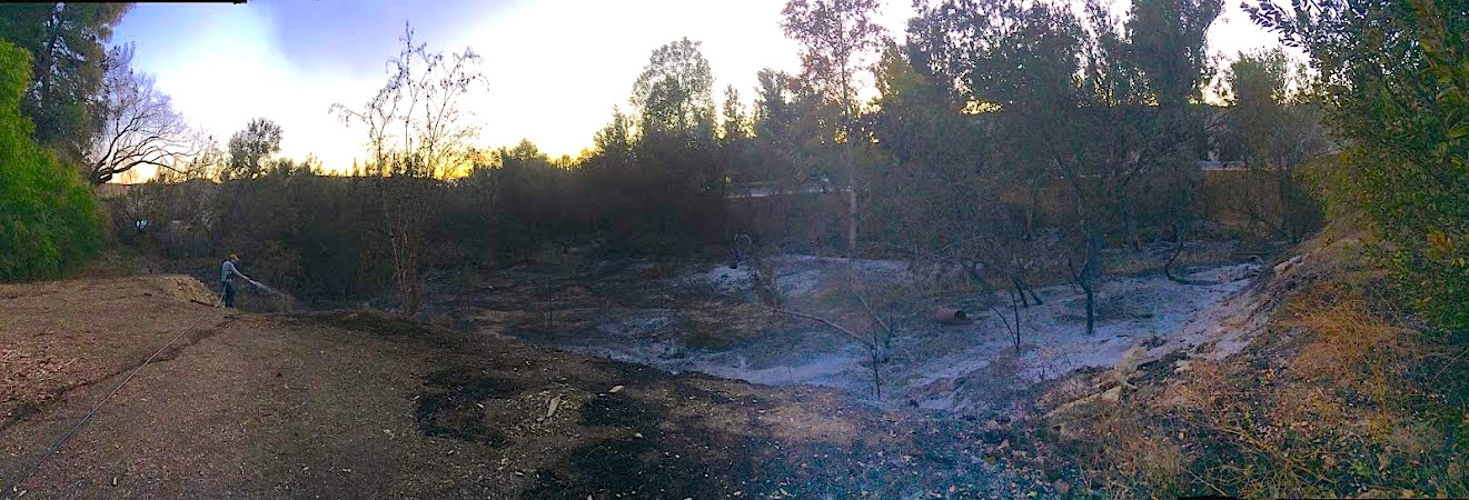
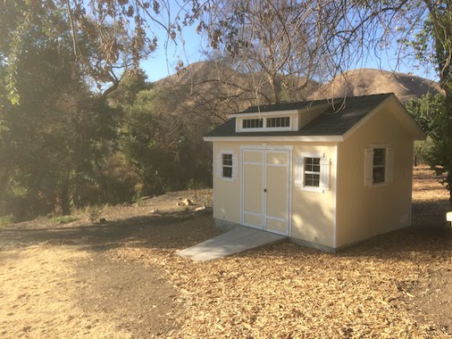
Two days after evacuating Lynn and I managed to get back to our house by hiking back. The Sheriffs didn't seem to mind if you walked by road blocks so we hiked four miles to get back to our house. It was lucky that we did because spot fires kept flaring up that could have done more damage. We patrolled our property three times a day for a week putting out spot fires. Old stumps buried underground kept burning for a month, stuffing a hose down in the ground would result in a geyser of steam. The recovery from the fire interrupted the airplane build for a month or so. We had to redo the plumbing for our well, repair our chipper, cement mixer and other equipment. We still need to build a new shed to replace the steel Craftsman shed. We'll build another shed from a Yardline kit that is wood construction. There is no satisfaction in building or tearing down those steel sheds.
27
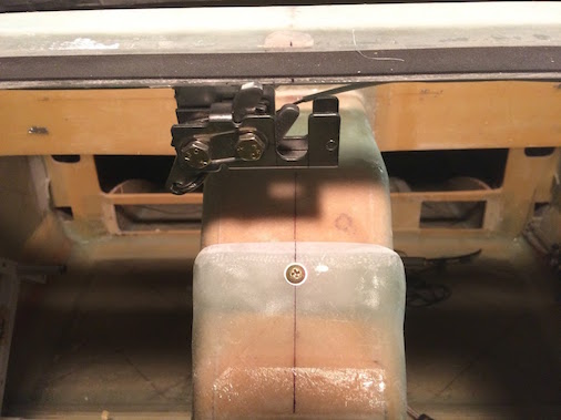
Here you can see all the brackets are floxed and glassed (2 plies BID) to the nose section and door. The J-hinge is riveted to the angle bracket attached to the door. The latch is also attached to an angle bracket with bolts threaded to a nut plate riveted to the angle bracket. The latch is SouthCo part number R4-10-10-501-20 purchased from Bisco Industries through Amazon. I initially ordered the wrong part number (right vs. left hand lever). Bisco provided the correct part number and let me keep the incorrect latch. SouthCo Part R4-10-10-501-20 Drawing
I used an 1/8 inch cable for a release and attached it to the latch with a thimble and crimp. I thought I would need another bracket to have the cable perfectly in line with the latch but I experimented with the cable pulling with an angle and it didn't take any more effort to pull than with it in line.
28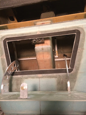
29
One problem is that the latch is in the way of removing the nose gear actuator cover. I've already had to cut the cover in half to make it fit through the access door. I may have to make it over.
The door was a bit flexible and with the latch pulling it closed in the center, the corners would warp up. So I added some stiffening ribs of 1/4 inch foam and 2 plies of Bid which eliminated flexing of the door.
Had a bit of a scare this weekend with the Santa Ana winds kicking up causing fires to the North of us. We also were having some trees cut down that didn't survive the fire from last year and one of the tree trimmer workers set his chainsaw down in some wood chips that started on fire. We immediately put it out but someone called the Fire Department so we had quite some excitement.
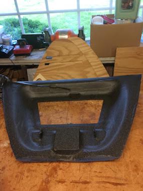
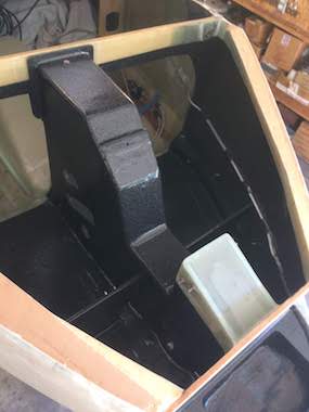
I have been working on the plane believe it or not, while also building a new shed and other fire damage recovery stuff. I can't imagine what it would be like if your whole house burned down. I've essentially completed the nose section, both the J-hinged access door and the little hatch in the nose is complete. Since it will be difficult to paint the inside of the nose section I did it now. In retrospect it may not have been the best idea since it made glass the nose top to fuselage a little more difficult to sand away painted areas that need to be glassed. I used Zolatone Lilith Gray, it turned out to be more black than gray, I'm not sure if I'll use that color for the main interior, I do like it but it may be too dark considering the temperatures that the enclosed cockpit might reach when parked on the tarmac. So I'm about to cut the canopy away from the turtleback but first need to build a frame to support the turtleback upside down.
Here are the paints I used, I purchased the Zolatone 20, Lilith Charcoal from from AutoBodyToolMart.com and the black primer and clear coat from, House of Klear, 818-504-4933, HouseofKlear@gmail.com, HouseofKlear.com (Website doesn't seem to be working now) and the electric sprayer from
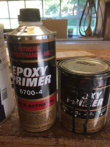
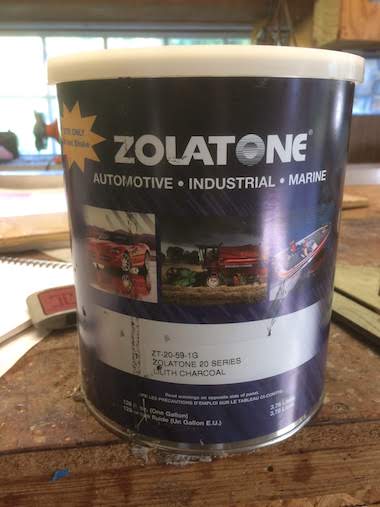
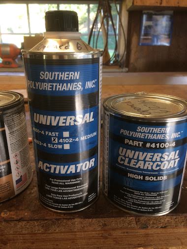

The painting was fairly straight forward, I first sanded everything with 80 grit sand paper and masked off where I thought I would need to glass joints. The black primer was actually pretty shiny and the Zolatone is fairly clear with colored flecks, you definately could not just spray Zolotone without the primer, it doesn't have enough color. The clear coat really makes it shine and from what I'm told really toughens up the paint job because Zolatone where's off in places that is often rubbed against.
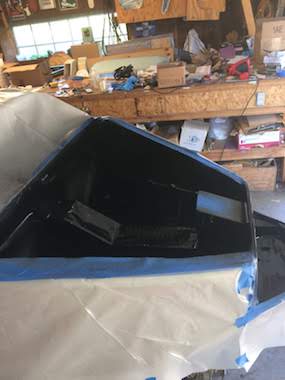
Here are some pictures of the paint job, I like it but I'm afraid it will be too dark for the interior of the cockpit. We'll see, don't need to paint that for awhile and the shock of the cost of the paint will have worn off.
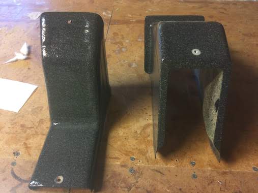
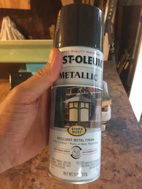
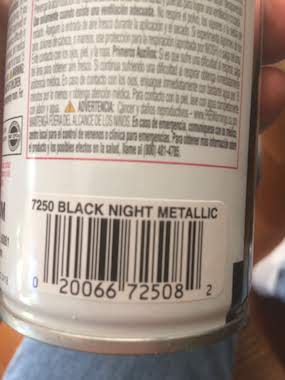
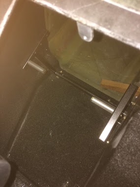
The rudder pedals came painted white which didn't look right with the dark Zolatone, so I found some spray paint, Rustoleum, 7250 Black Night Metallic that makes them blend in nicely.
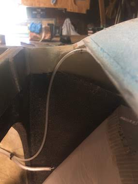
In preparation for glassing the nose top on I needed to figure out how to route the nose door release cable conduit, my initial plan was to route it along the top of the fuselage wall but that would mean making a small divet in the top of F22 bulkhead which was not recommneded by Rick Hall or Marc Zeitlin, so I routed it in an "S" curve which didn't add too much extra drag on the cable.
Here are pictures with the nose top and nose cone finally glassed to the fuselage with a smooth sloping transition.
So the nose door release works and latches fine. The nose cone hatch is also removeable with this 1/8" aluminum rod (red arrow).
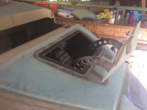
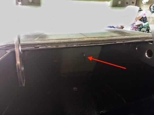
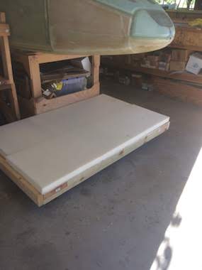
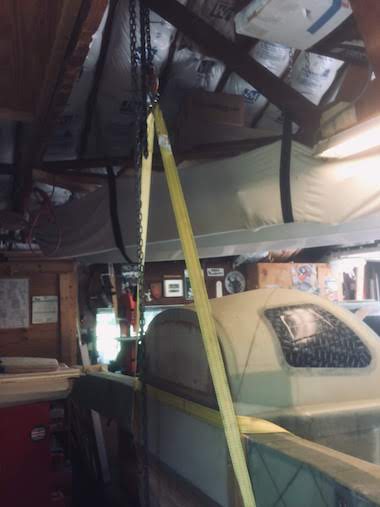
Pull the rod out and you can grip the aft edge of the hatch and pull it free, this is also a Rick Hall design. I also made a rolling flat bed to put the fuselage on so that I can open the canopy on the fuselage with clearance from the garage rafters and kayak hanging from the rafters.
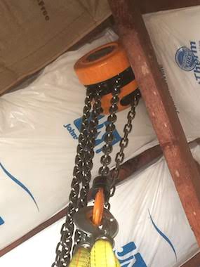
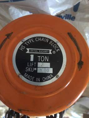
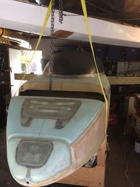
The fuselage has gained enough structure that it's awkward for Lynn and I to lift it. I thought I could just lift it with some rope and pullies but it was still too heavy. I looked around my father-in-law's garage for bigger pullies but then Lynn found this chain block in her brother's garage (we all live next door to each other) it makes lifting so easy, I purchased a second one ($60) and some straps from Harbor Freight Harbor Freight Chain Block I had a 20% off coupon so it was really only around $40. Now I can lift and lower the fuselage completely by myself.
One final task to the nose section is a torsional brace between the nose top and bulkhead F22. It's just 3/8" PVC foam with a ply of BID on top and bottom. I used some shims and drywall screws to hold it in place. I thought there should be a flox corner on the aft edge of F22 but Marc Zeitlin said it was not necessary and only adds weight.
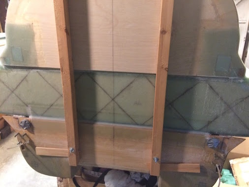
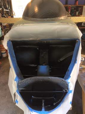
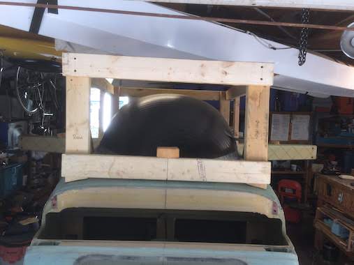
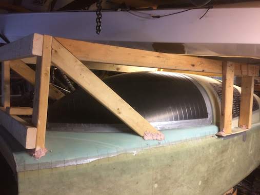
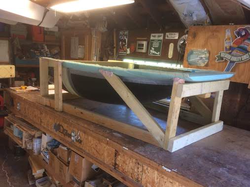
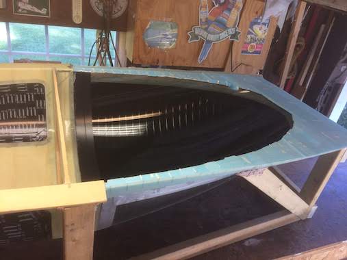
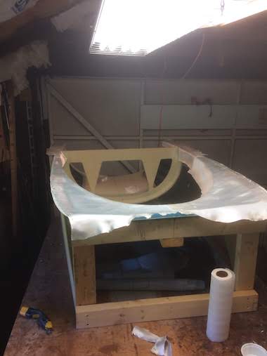
In preparation of separating the canopy from the fueslage I built a 2x4 frame per the plans with one additional up right on each side, many builders find the the canopy warps after being separated so having more supports is better. The wood frame will be bondo'd to the canopy after separation.
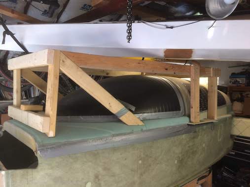
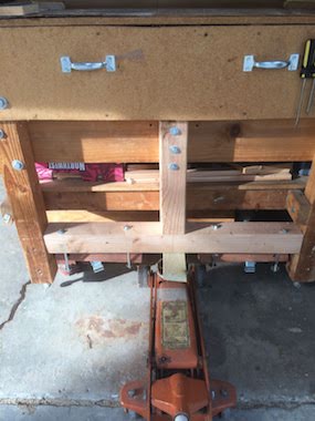
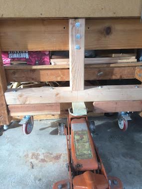
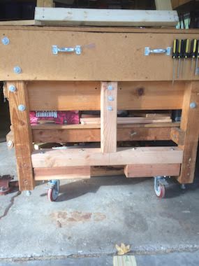
I wanted to make my workbench moveable since space is becoming more and more restrictive especially with having to separate the canopy from the fuselage. I found this configuration on the Internet (pictures from internet not mine) and implemented it but the hinges were not up to the task, they were easily bent.
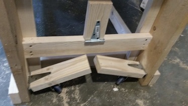
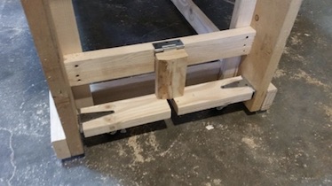
So I came up with this configuration where the hinges are merely a convience factor, a floor jack does all the lifting and bolts go through both 4x4's to handle the torque of moving the bench around. The wheels are from Amazon ($32.00 set of 4) and rated at 450 lbs each so total of 1,800 pounds, I think my bench may be just over 1,000 pournds. To the bench I just added the inverted "T" 4x4's and hinged the 4x4 blocks with wheels to the bottom, matched drilled 3/8" holes for bolts to hold the hinged blocks with wheels in position while moving the bench around. Pull the 3/8" bolts out of the hinged blocks when wheels are retracted. Still takes some pushing and pulling to move it but at least I can.
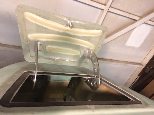
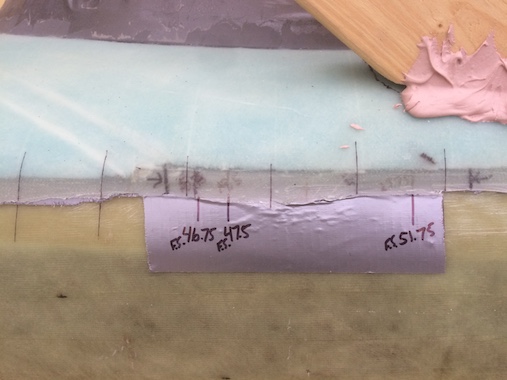
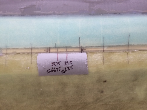
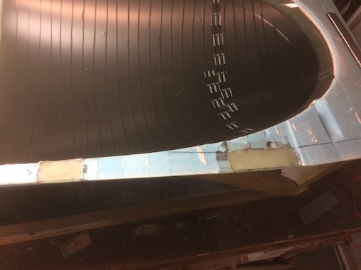
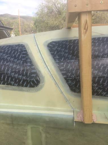
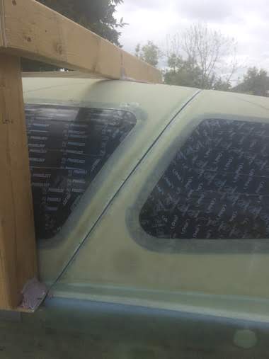
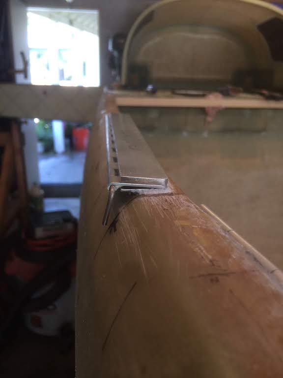
So with the frame bondo'd to the canopy the only thing left to do was to cut the canopy between the aft two windows. I made a lot of alignment marks for future reference. I used my Fein sander to make the initial cut, I needed to be careful to not cut through the drip rail and the longerons at the base. It was a little tricky cutting the corner where the canopy side wall transitions to base over the longeron, luckily I had a square Fein sander blade that could fit in the corner. Once the initial cut was made it was followed up with a hacksaw blade to hand cut all the way through until it was possible to feel the drip rail.
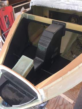
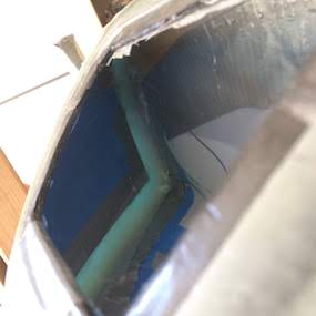
Lynn and I lifted the canopy/frame off the fuselage and to the work bench, it took a little prying and bumping to break it loose from the micro blobs that held it on. The frame makes it a bit heavy as I added some additional bracing to ensure the canopy would not warp, many builders recommended to do this. The aft portion of the canopy or turtleback was already permanently glassed to the fuselage on the outside but now the inside joints need to be glassed and also the top side of the center spar needs to be glassed to the upper firewall
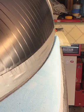
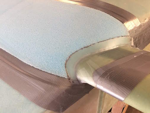
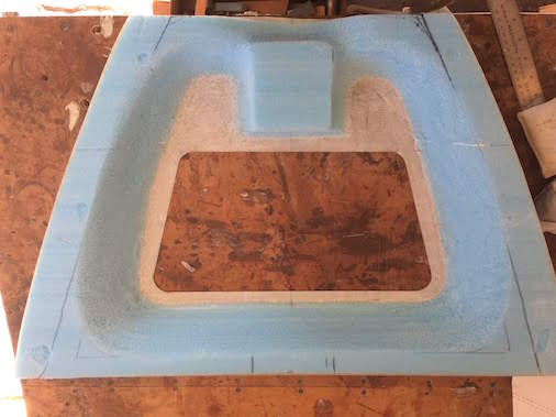
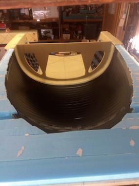
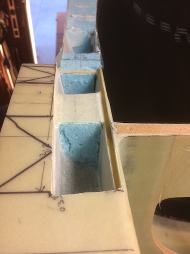
The blue foam will need to be shaped and glassed, overlapping onto the plexiglass. If you remember when making the canopy frame I made it so that there would be a 1/4" gap between the top of the longeron and the bottom of the canopy frame to allow for a rubber seal to be installed, this was a recommendation from Marc Zeitlin. I'm not quite sure how this will be implemented especially with the latching hardware and hinges along with the widened canopy, modifications are always a head scratcher.
Tuesday, October 22, 2019
With the interior of the canopy now exposed the first thing to do is protect the plexiglass, like I did with the outside. I used 3M, 2" wide tape with a 20 mil thickness, normally used for wrapping plumbing pipe to prevent corrosion. The Cozy email group claims that when this tape is removed it doesn't leave any adhesive stickyness on the plexiglass. I do like that it is fairly thick so it can handle bumps to the plexiglass.
Wednesday, November 27, 2019
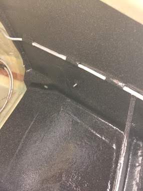
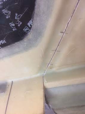
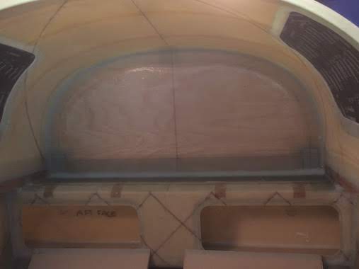
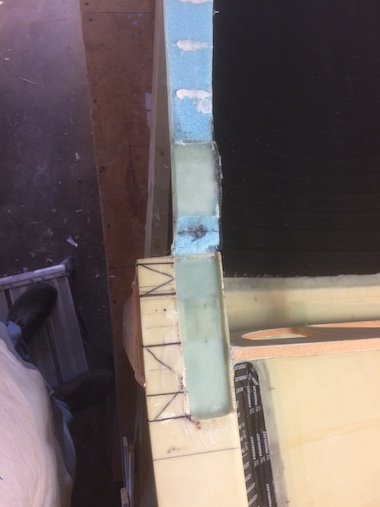
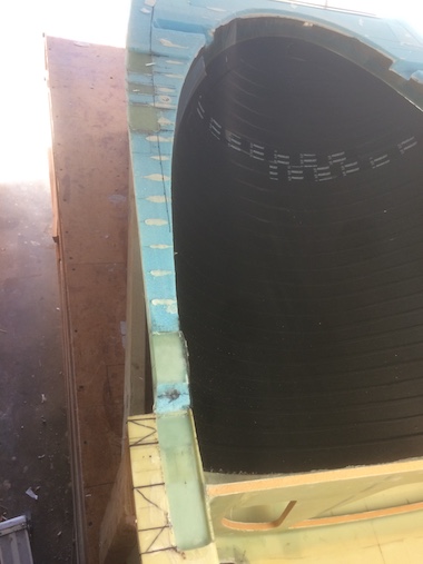
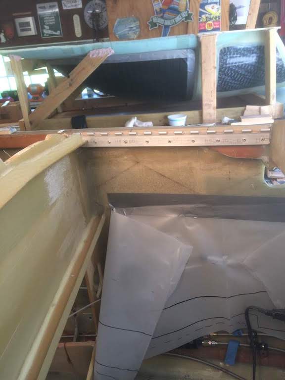
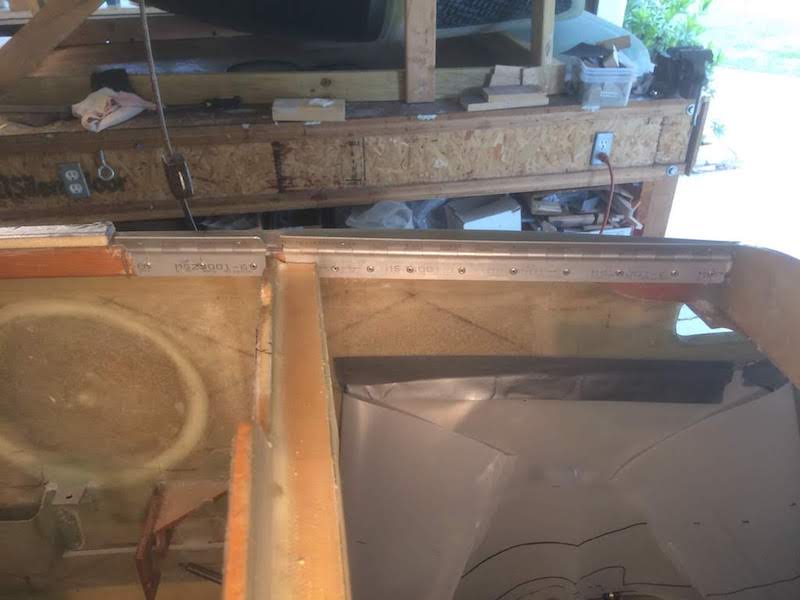
So after cutting off the forward section of the canopy I need to finish off the leading edge of the turtle back which acts as a rain gutter. The jagged foam was smoothed out with a flox corner on the upper edge then 2 plies of BID was applied. The joints between the turtleback and firewall and longerons also got 2 plies of BID.
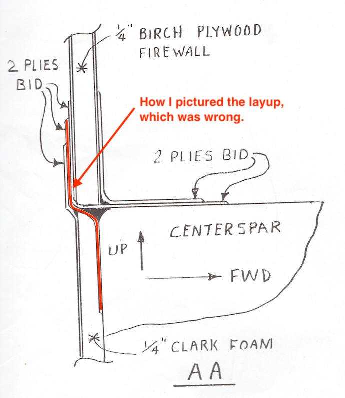
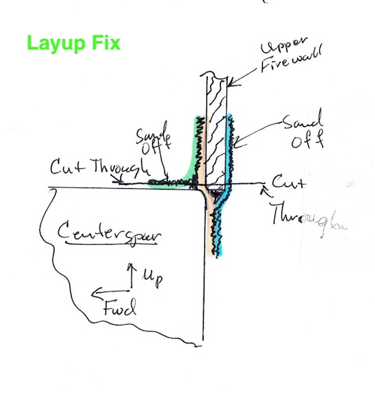
Then we did the layup between the lower edge of the upper firewall and the centerspar. After everything was nicely cured I started thinking about the layup and had a bad feeling that how I had done the layups was not the same as the lower firewall to centerspar layups. After checking the drawings and plans I realized I had misinterpreted cross section A-A on drawing M7 as you can see from the figures below.
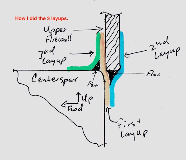
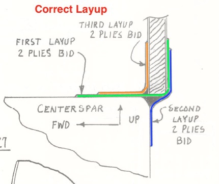
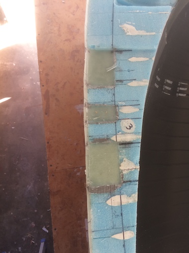
I posted to the Cozy email group whether this would be a problem and Marc Zeitlin recommended to redo the layup, because without the first 2 ply layup from the aft face of the firewall to the top surface of the centerspar there is no peel resistance to the joint and since it would only take an hour to remove the layup with a dremel grinding wheel to just do it over. Here is exactly what he said, "First, the theory. Composites are great in tension, compression and shear, but you don't want to ever put them in a "peel" condition (like pulling tape up off a surface). The purpose of the 1st 2 ply layup that went from the aft face of the firewall to the top surface of the spar was to ensure that if anything ever pushed aft on the firewall, this tape would prevent any motion and peel of the 2nd and 3rd layups. Without that layup, there's no peel resistance in the joint. Now, I cannot think of anything that would CREATE a peel condition in that joint - no flight loads, generally, and although a high "G" maneuver might pull aft hard on the top engine mount hardpoints, they're in the corners and there's so much glass over them that peel really isn't an issue. These are the kind of questions I hate. The RIGHT answer is to remove the existing layups without damaging the aft or top surface of the spar in any way, and then apply the correct layups, but it's possible that in attempting that, you could do damage to the spar, and that would be a LOT worse. Now, it's difficult for me to imagine a case where having the layups as you do could possibly be a problem, but just because I can't imagine something doesn't mean that it can't happen... Since we're only talking about 3 ft worth of 6 plies of BID, it probably wouldn't take an hour to remove it with a dremel grinding wheel or the equivalent. I recommend replacing the layups, but I'm not hard over about it unless someone can think of a reason why my logic above is faulty." So when Marc recommends something, you do it, and he always gives a technical reason to support his advice. I was able to cut through the layup with my Fein sander, it took a couple of hours and I was careful not to damage the center spar which already had 2 plies of BID on it anyway (from the incorrect layup) where I was cutting so it was protected. After cutting through, between the top of the centerspar and the bottom of the upper firewall, I sanded the previous layups to accept the new layups correctly applied. I didn't sand the previous layups all the way down since it would've been a lot of hand sanding, leaving them adds a bit of strength and only a little extra weight.
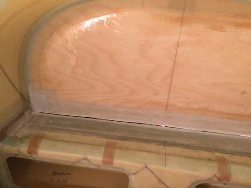
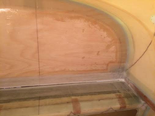
Now the three layups are correctly applied and all is well again.
Next is to apply 8 plies of BID to the inside corners.
Wednesday, Jan 15, 2020
I did the 8 plies of BID in the corners one ply at a time, placing each ply of BID dry and then wetting out with a brush. I used a piece of wood 4"x4"x18" with rounded corners and covered in duct tape to shape the BID cloth (dry) around to take on the shape of the corner and then placing in the corner. An idea suggested in the Cozy email group. The BID cloth pieces were oversized at 12"x15" cut at 45 degrees. I did each corner separately as it took 2.5 hours for each corner while being crammed in the back seat. Once both corners had cured I floxed in the 1/4" thick aluminum engine mount hard points with one ply of BID over them. They are a little goldish brown in color due to the alodining.
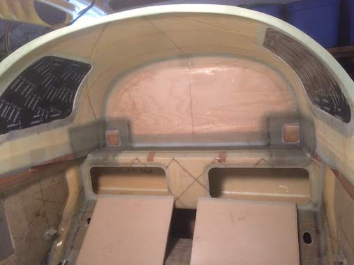
I also finished off the firewall by floxing in the plywood end pieces with blind mounting screws (made in chapter 4 over 15 years ago) and filling the space in-between with 1/4" Clark foam and covering it all with 2 plies of BID overlapping everywhere by an inch.
425Sunday, March 22, 2020
With Covid19 in full swing and everyone ordered to stay at home or at least away from other people, "social distancing", I decided it's a good time to update the website, although for us retired folks that are homebodys anyway it's really no different except that there's no toilet paper available.
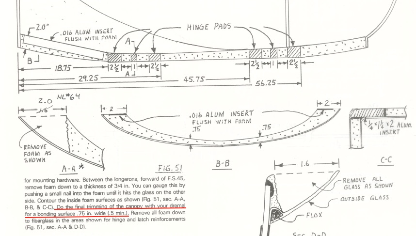
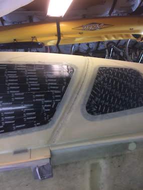
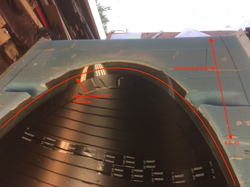
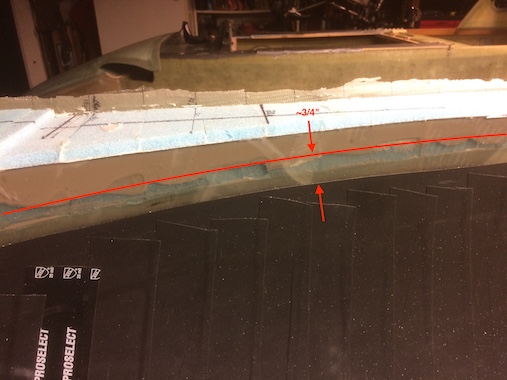
Now it's time to turn to the canopy and finish the underside of the canopy frame which is still fragile exposed foam. The underside needs to be shaped smoothly to provide clearance for the instrument panel which is where the two retangluar cutouts are which was done in the original shaping of the foam blocks. The plans say that the foam should be 3/4" thick in the front section of the canopy about 17 inches (Fuselage Station FS-45) from the front edge and to use a nail marked with 3/4" as a depth gauge. Once I started to get an idea how thick the foam really was, two inches in a lot of areas I realized that plexigass when again need to be trimmed to get the foam down to 3/4", which was stated in the plans, (underlined in red). I thought, you got to be kidding, the stress of trimming it again! Also then the foam lip over the plexiglass would be gone, but there was nothing else to do. So I cut the plexiglass along a trim line that would allow the foam to be shaped down to 3/4" and then with a thin Fein sander blade cut between the plexiglass and the foam so that huge chucks of foam wouldn't get pulled out when removing the cut plexiglass.
At this stage you also need to hog out the foam in the areas for hard points where the canopy hinges and latches will be bolted on. I wanted to be sure my locations on the canopy would line up with measured locations on the fuselage so I did a canopy fit check on the fuselage and the locations lined up. Doing these fit checks isn't easy since I really over built the wood frame holding the canopy so it is really heavy for Lynn and I to lift onto the fuselage.
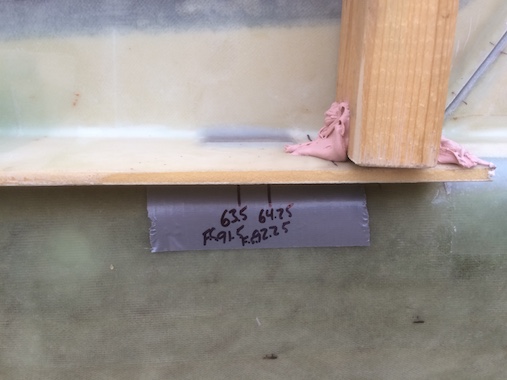
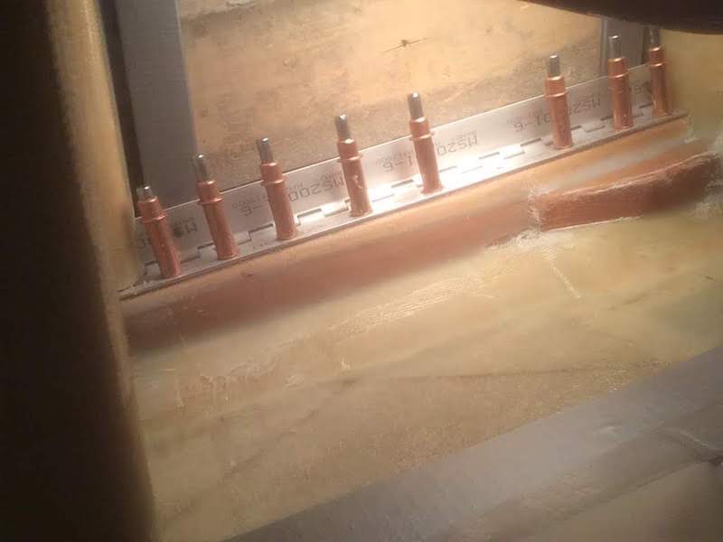
Here you can see the hard point locations with the foam hogged out to the upper fiberglass skin.
Now the hogged out hard point locations are filled with alternating layers of fiberglass and wet flox, the plans say to get at least 15 layers of fiberglass in, we ended up with about 20 or more.
Here are pictures after doing the final trim of the plexigass canopy, I used white electrical tape to mark the trim line.
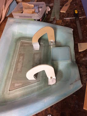
The forward section of the canopy frame gets a 0.016" thick aluminum strip 18" long by 1.6" wide along the sides. I believe it's to have something to rivet the attach hinges to for the removeable fuselage top, the plans don't really say what the aluminum strips are for. I taped plasitc along the front and sides so I could make a template for cutting the fiberglass that would be layed up.
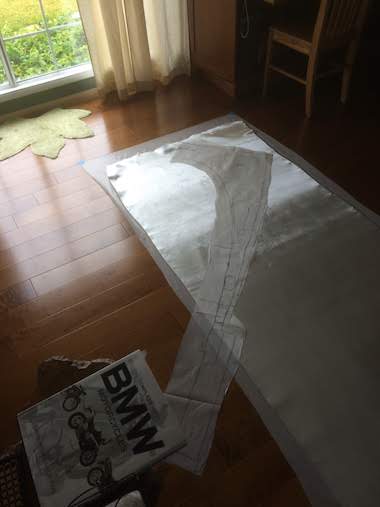
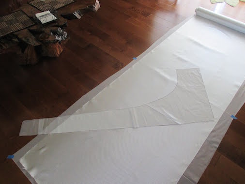
I had to cut the fiberglass cloth on the living room floor, since you want to have as few overlapping pieces as possible. I also did a final fit check of the canopy back on the fuselage to make sure there was no interference anywhere.
Made sure the canopy to turtleback interface was still in alignment (both sides).
Here is the first ply of BID cloth going on, the total layup was 2 plies of BID and 2 plies of UNI, it took Lynn and I six hours to do it.
The completed underside of the canopy frame.
481Saturday, March 25, 2020
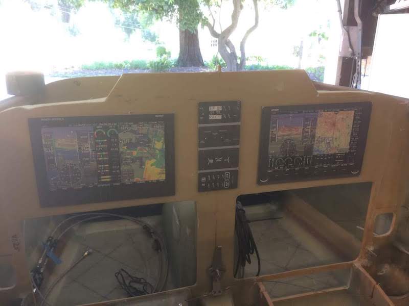
Had a some fun printing out full size display layouts from the Dynon website. I mounted them on cardboard and taped them to the instrument panel, I think it looks pretty good. I had fooled my brother and friends by sending them a pictue saying I had installed my displays, it was April fools afterall.
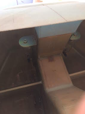
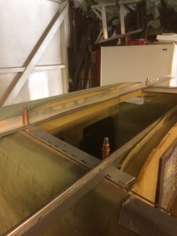
I also floxed and glassed (2plies BID) the wood doublers (both sides) between the Instrument panel and F28 which the hinges that hold the fusleage top get riveted to. Needed to make sure the hinges are flush with the top of the longeron so they are clecoed (removeable fasteners) to some aluminum angle bridging both longerons.
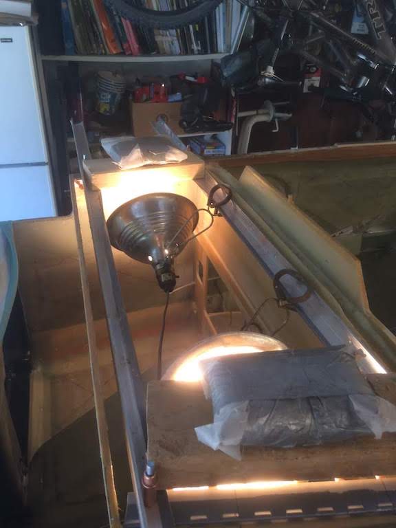
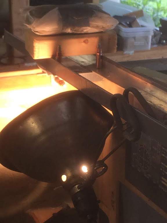
Once everything is set the hinge is floxed to the doubler and held in place with more clecos. The lamps are to warm up the flox for a good cure.
Was two clecos short, so missing one cleco on each side, no problem.
Another short 4 inch piece of hinge is added just aft of the instrument panel. I angled it a bit with a flox pad so it would line up with the front hinge section since the hinge pin has to go through both hinge sections.
Here you can see both hinge sections floxed and riveted in place with the hinge pin going through both sections traversing the instrument panel. Never thought you could pop rivet into wood, but it works especially with a few plies of BID glassed to the wood.
I had removed the canopy hinges from the top of the longerons so the foam for the canopy frame would be flush. In hind sight it was really unnecessary could have just recessed the foam for the hinges, the plans didn't say to do that but sometimes you just need to use common sense. So I floxed the hinges back on, made sure they were in alignment using a level as suggested in the plans. I also made some 1/8" aluminum spacers since I had created a 1/4" gap for weather stripping along the sides of the canopy. The hinge thickness is about an 1/8" and with the 1/8" spacer it should come out equal, we'll see.
Here you can see the dreaded overhang of the hinge beyond the side of the fuselage, an endearing characteristic of the Cozy airplane. Even the plans say that the hinge will overhang the fuselage side. Basically unavoidable if you place the hinge at the plans locations and have them in alignment. Some builders have gone to extreme measures to minimize this affect, but I'm just going with it. Maybe I'll glass a little stream line fairing to blend it in.
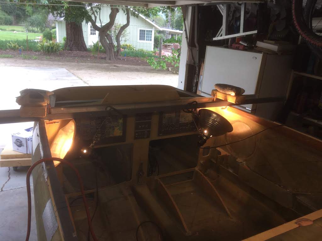
Wednesday, Sept 9, 2020 I used the chain block to raise the fuselage off the cart to a lower rolling platform I made so there would be enough head room to open and close the canopy without hitting my kayak hanging from the rafters. |
 |  |
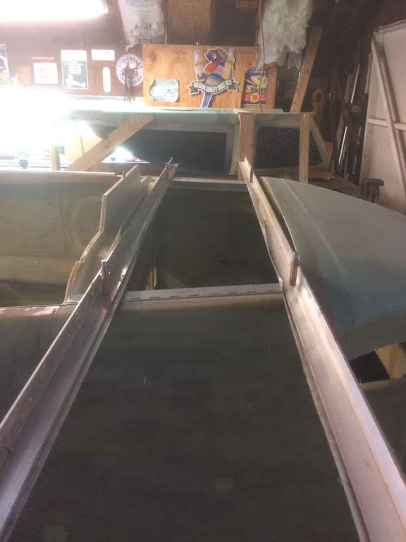
| Here you can see the fuselage sitting on the lower rolling platform. I've also cut the foward fusleage top from the canopy. This was something I was really stressing about but turned out not to be such a big deal. I used a jigsaw angle at 45 degrees and made the cut. | 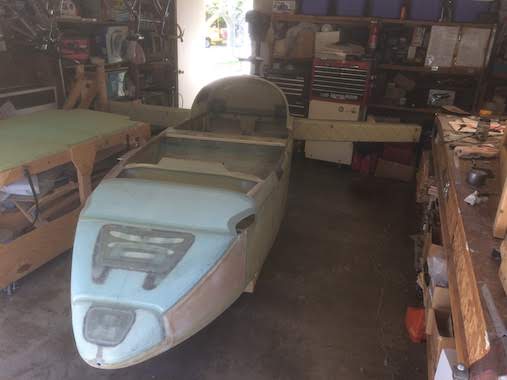 | 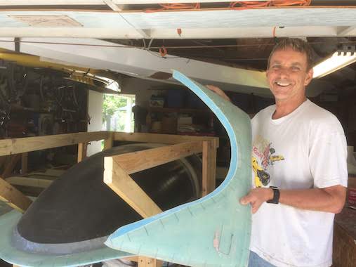 |
| To avoid cutting into the fuselage sides and instrument panel I set the canopy on my rolling cart with the front hanging over, Lynn held the front while I made the cut. Drew a lot of alignment marks. Very happy with how it came out. | 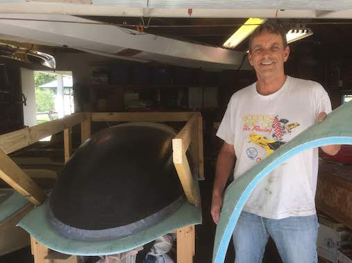 | 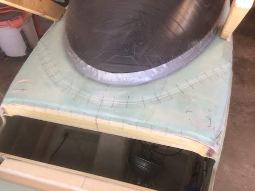 |
| This is the jigsaw blade I used, it needed to be pretty long to cut the thickness of the 45 degree angle. | 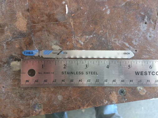 | 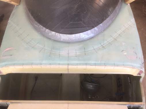 |
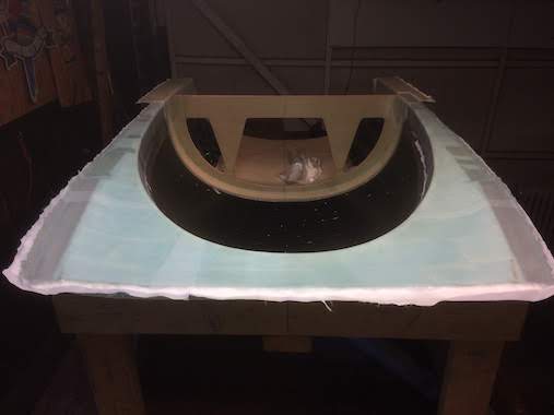
| Finally could check that the canopy hinge actually worked. Bondoed the front fuselage section to the canopy with popsicle sticks and reattached the 2x4 frame to the front section so I could flip it over and glass the underside. | 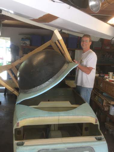 | 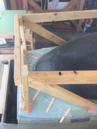 |
| The canopy is now flipped over on my bench and an inch and a half lip of 2 plies bid is glassed to the underside. The second picture shows the front section detached from the canopy and the glassed lip. | 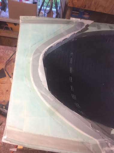 | 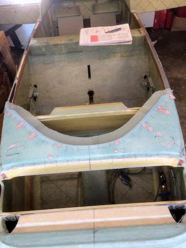 |
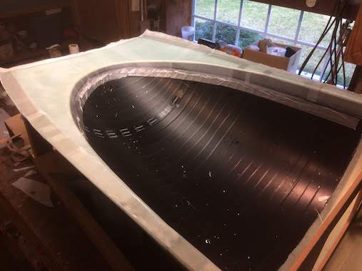
| Now the top side is glassed with 2 plies BID. | 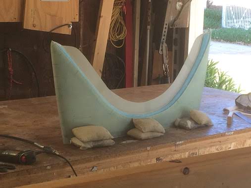 | 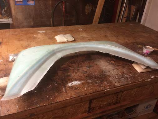 |
| Finally the edge of the canopy is glassed with 2 plies BID. Also made the instrument panel cover by shaping some foam and covering with duct tape. | 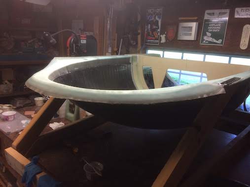 | 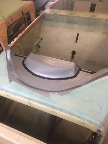 |
| Here you can see the finished instrument panel cover. The second picture shows fiberglass tabs pop riveted to the cover that will clip onto the front fuselage lip. | 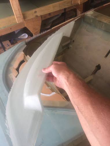 | 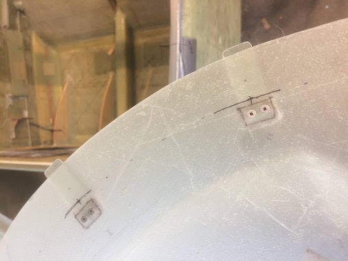 |
| Here you can see how the instrument panel cover clips to the front fuselage top section. The cover also has two tabs to screw it to the instrument panel. The instrument panel has threaded 1/4" aluminum slugs embedded to accommodate the screws. | 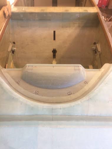 | 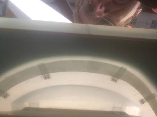 |
| Here you can see the three latches installed that latch the canopy closed. The second picture shows the third angle bracket that needed to be relocated inboard of the canopy wall which was due to the fact that I widened the canopy from the plans dimensions which is a common change. | 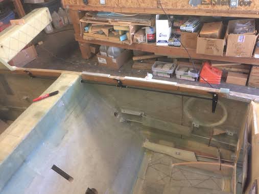 | 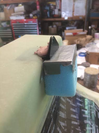 |
| I maded a fiberglass bracket with a 1/4" aluminum plate embedded to screw the third aluminum brakcet to. If I recall correctly it's about 16 plies of BID thick. | 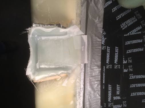 | 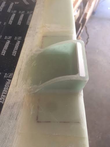 |
| Now to finally drill and countersink the holes through the hard points to hold the first two angle brackets. I was concerned that I might drill into the plexiglas canopy so I made a little jig to see where the hole would exit the canopy frame. This worked out really well and gave me confidence that I had adequate clearance from the plexiglas canopy. | 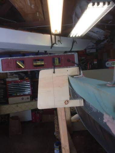 | 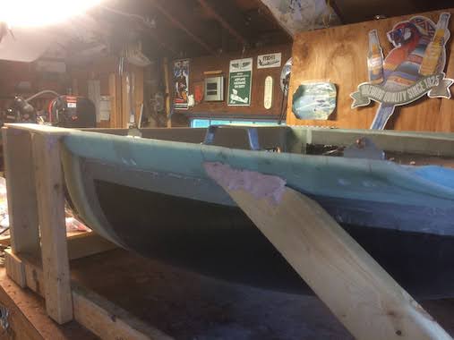 |
| Here the angle brackets are floxed and screwed in place along with the canopy handle. For the canopy handle I had embedded 1/4" aluminum in the hard point. So I drilled the holes undersized to thread the aluminum and then enlarged the hole up until the threaded aluminum for the screws. | 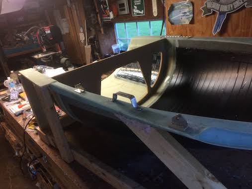 | 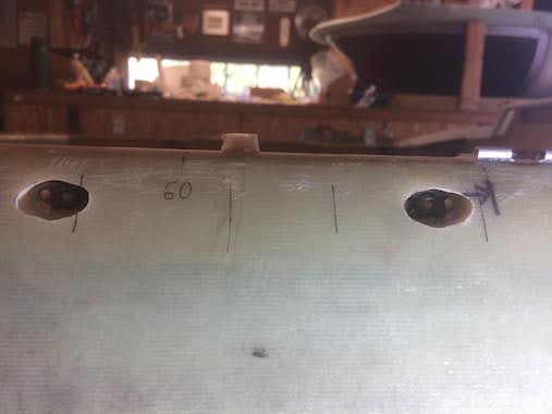 |
| Here the third (most aft) angle bracket is floxed and screwed down to the inboard fiberglass bracket. The second picture shows the Jack Wilhelmson rotary latch installed. | 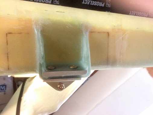 | 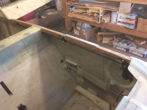 |
| A close up of the rotary latch installed. I really thought I followed the directions to a "T" but I really didn't understand how the latch really worked. See the video asking the Cozy group if how I installed it made sense. The response from the group was that the rotary latch was very difficult to adjust correctly and Marc Zeitlin recommended the "Shark Latch" so I abandoned the rotary latch for the shark latch. | 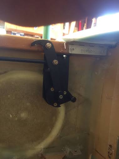 | |
| The right side headrest needs to be installed to provide an attach point for the canopy gas spring. I noticed that the head rest (built probably 15 years ago) overlapped unto the hard points for the shoulder harness attach points. Turns out the distance for the attach points was narrowed at some point so that the harness straps won't slip around your shoulders in an accident. So the headrest needed to be notched to allow for the harness strap attach buckles. | 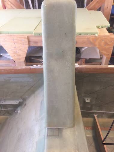 | 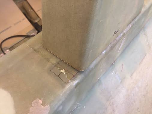 |
| This is the canopy safety catch in case you for get to latch the canopy this will catch the canopy from opening further than about an inch. | 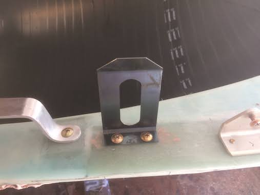 | 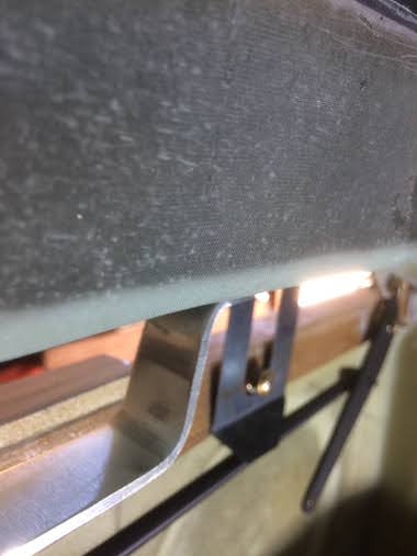 |
| The right head rest is glassed onto the seat back and a 1/4" piece of aluminum is embedded to provide a mount point for an angle bracket to which the gas spring ball joint will be bolted on. | 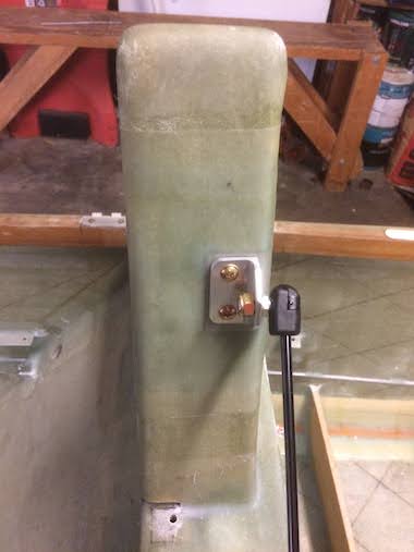 | 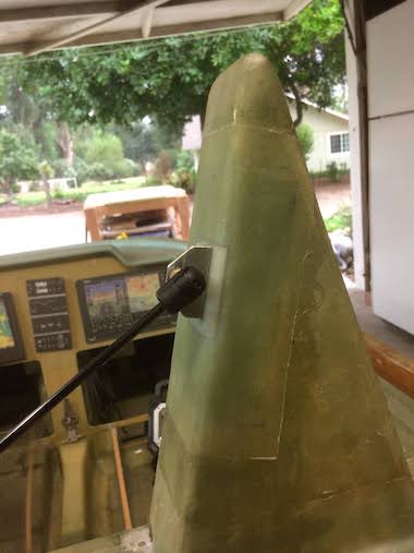 |
| Here are so more pictures of the gas spring attach point. I ultimately followed the plans dimensions for the attach points, I was thinking of mounting the gas spring to the seat back, and have both headrests glassed to the canopy like the pilot side but it became too complicated. The second picture shows the attach point on the canopy side. It also has a 1/4" piece of threaded aluminum embedded to bolt the gas spring ball joint to. What's nice about the plans location is the gas spring is extended in both the canopy open and closed positions which helps keep the canopy closed and also extends the life of the gas spring. | 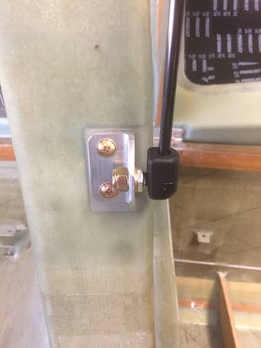 | 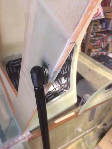 |
| Opening and closing operation of the canopy gas spring, like magic! |  | |
| I bought the gas spring from Amazon it is 15" extended, 9.5" compressed with 40 Lbs force and only $23.99 for a pair. The specifications are per the plans. | 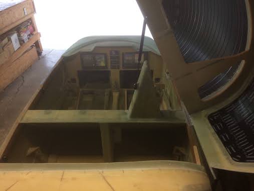 | 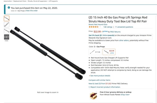 |
| I needed to install the canard to check where the trailing edge would be relative to where the side air vent intake ducts would be located, so it was a good opportunity to see how everything fit, looks pretty cool! | 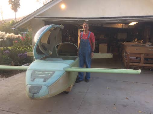 | 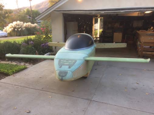 |
| Decided it would be good to have a little more fire fighting defense besides a garden hose. So we installed a 3,000 gallon water tank and bought a Davey Firefighting pump. I mounted the pump on a little cart and it's ready to go. See the video to watch it in action, it's got quite some pressure! | 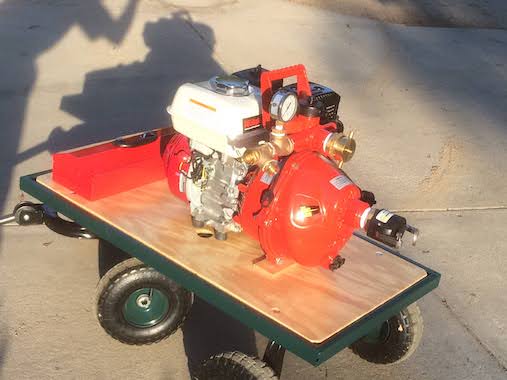 | |
| My brother, Jon had the first flight of his homebuilt airplane, a Sonerai on October 9, 2020. Way To Go! | 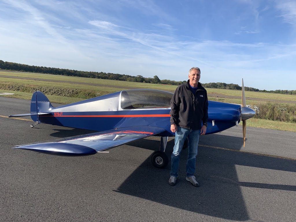 |
| The months of October and November of 2020 were occupied with the repair of an oil leak on my 2001 BMW K1200RS. It turned out to be the rear main engine seal leaking. To replace that required taking the rear half of the drive train out. While everything was apart some other items also needed replacement, the clutch slave cylinder leaking fluid into the transmission which required all the transmission seals to be replaced. There was a pool of oil on top of the engine because of a dried and broken rubber crankcase breather manifold. A seal in the rear drive was starting to leak so it was also replaced. Also replaced the spark plugs and checked the valve clearances. The Clymer manual was indispensable and made the work fairly straight forward. To get the transmission out you need to loosen the engine mounts and raise the rear of the frame. Luckily my chain blocks came in handy for this. | 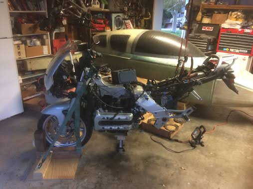 | 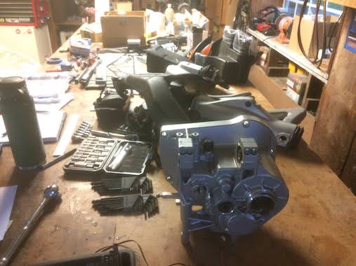 |
| Here's the Beemer all buttoned up with the fairings or the "Tupperware" as it's called back on and a video of the first engine start. Have put about 300 miles on the bike since the repair and so far, no leaks! I'm really amazed, I normally don't have much success with things that leak. | 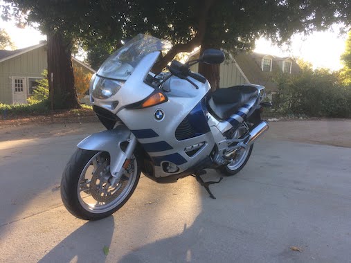 | |
Jan 18, 2021 Now back to finishing the canopy. I bought some "eyeball" air vents from Aircraft Spruce, you can really pay whatever you want for these things, I got this one for $60 each, still pricey for an air vent but are nice anodized aluminum. I installed them close to the plans locations I needed to adjust a little inboard so that I'd have room the new type of canopy latch, the "Shark Latch". | 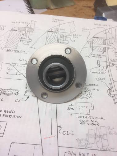 | 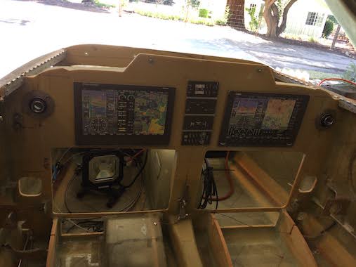 |
| Fabricated air vent scoops per the plans shape and dimensions. First shaped some urethane and covered with duct tape. | 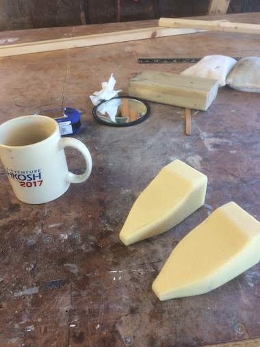 | 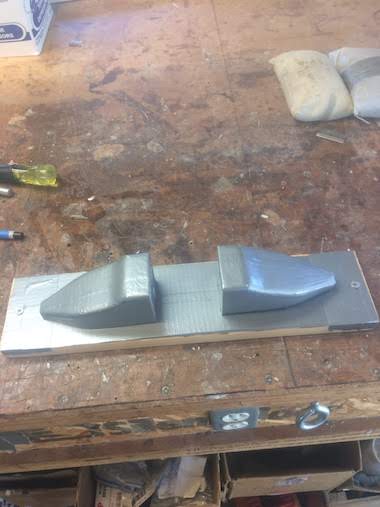 |
| Covered the shapes with two plies BID and trimmed to the final dimensions. | 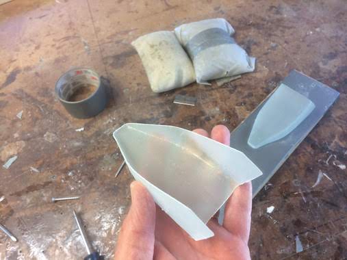 | 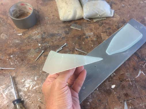 |
| The air enters through the fuselage side just aft of the canard trailing edge. The plans have a template for NACA air vent shape. Always fun cutting free hand into a nice smooth fiberglass fuselage side. The leading edge is not cut to retain the flap and create a smooth blended leading edge | 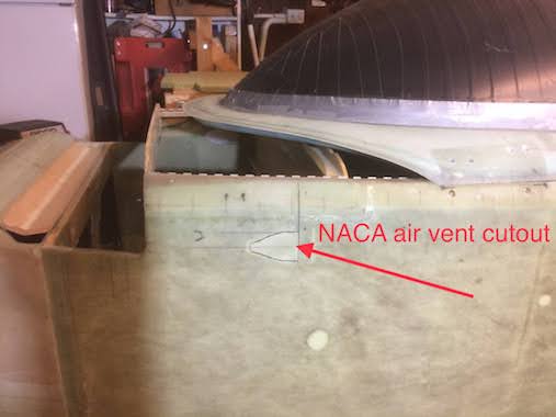 | 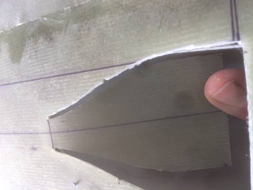 |
| On the inside a 1/4 inch glass border is routed out and 1" at the aft end. | 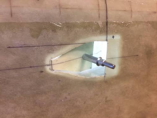 | 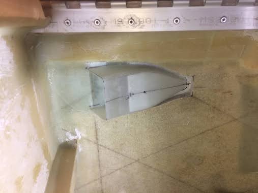 |
| The finished NACA air vent. | 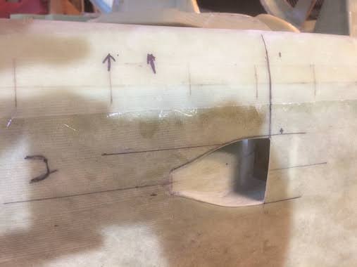 | 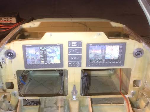 |
| Now just to duct the air to the vents on the instrument panel. Used some blue foam to fabricate the very short ducts. Initially I thought I'd just block of the corner of the back of the instrument panel and fuselage side and formed the blue foam to do that. Then once I had that formed that it didn't seem to be much extra work to make it an actual duct, so that's what I did. Then I covered the blue foam with duct tape and glassed it with 2 plies of BID. | 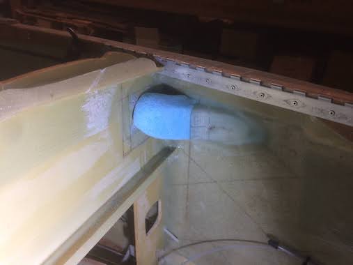 | 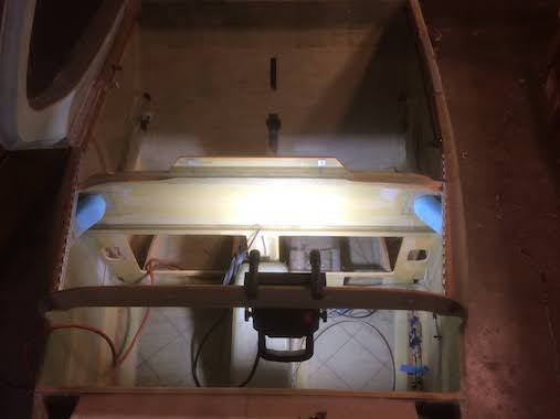 |
| Here are the two ducts after hogging out the blue foam and fitted into place. | 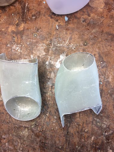 | 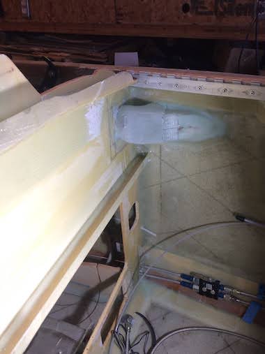 |
| More pictures of the air vent and a shot through the duct. | 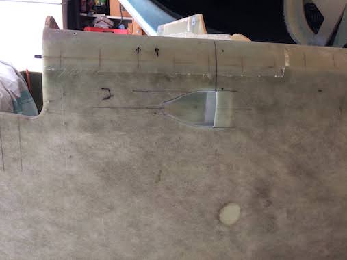 | 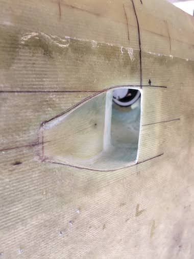 |
| The ducts glassed in and complete. | 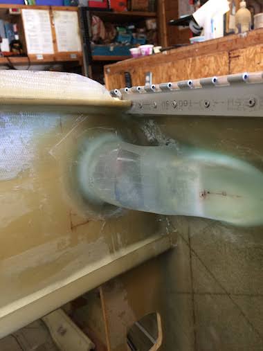 | 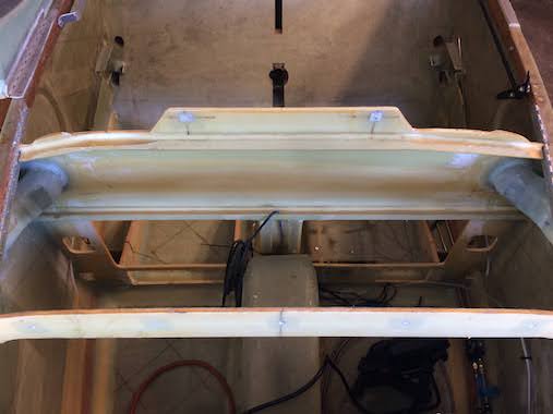 |
| So back to the canopy latch and the design recommended by the Cozy group and Marc Zeitlin was the "Shark" latch. Bob Forstner had refined the design and was gracious enough to send me the drawing. The drawing was a .dxf file so to open it I used Autodesk Viewer where you can create a free account. I used the measuring tool on the Autodesk viewer to get the dimensions then I printed it out several times with different scaling percentages until it printed with the correct dimensions. I 3M sprayed the print out to 1/8" aluminum and cut out the parts and drilled the holes, worked perfectly. | 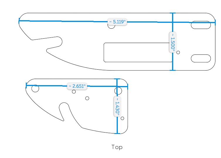 | 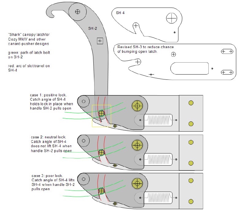 |
I glassed a couple of Click Bonds to the instrument panel and made a braket from aluminum angle to attach the Shark Latch. | 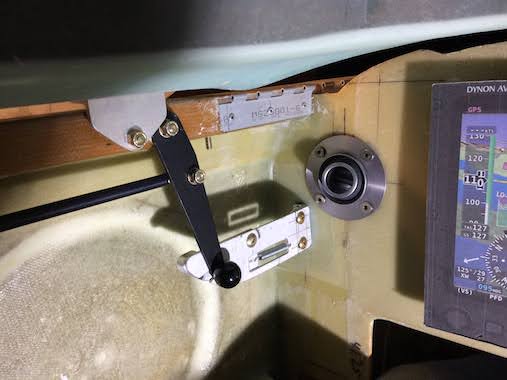 | 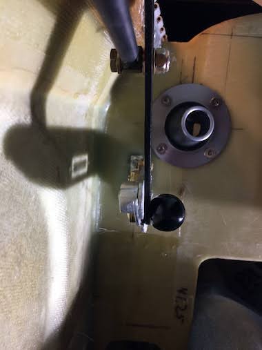 |
| I still wanted a way to lock the canopy and Marc Zeitlin showed how he did it here: Marc Zeitlin Updated Canopy Lock. He used a barrel lock p/n 1682A21 from McMaster-Carr, so I ordered the same one. | 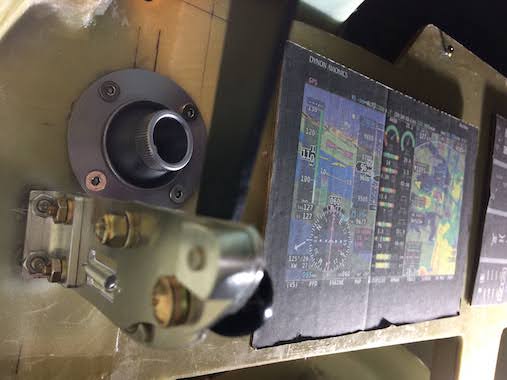 | 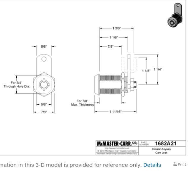 |
| The tricky part was figuring out where to to actually put the lock. After some fiddling with the lock and the latch linkage I decided on a spot and built it up with about a 1/2" of fiberglass. I hogged out the foam to the outer skin and floxed in the solid block of fiberglass. After cure I used 7/8" & 3/4" counter bores to get the lock flush with the outside skin. I also notched the back side to flox the anti-rotation plate in place. | 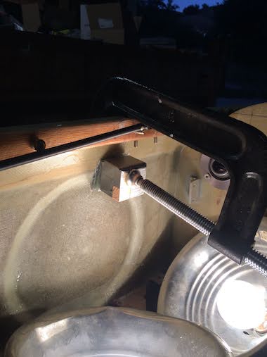 | 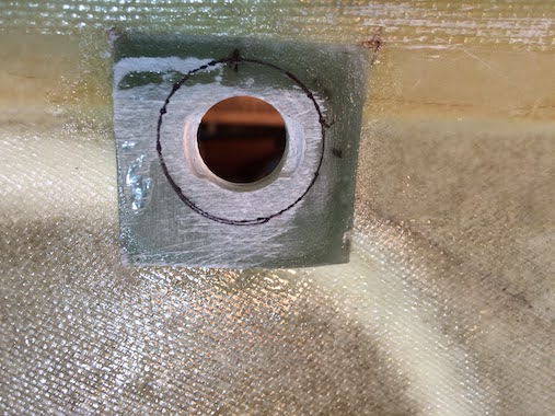 |
| Here is the anti-rotation plate provided with the lock. |  |  |
| The fiberglass block shaped and glassed with 2 plies BID to side of fuselage. Lock arm in locked position preventing canopy latch from being moved. It's still possible to lift the canopy about 1/4" since the canopy handle is not latched into the shark latch. You don't want the rotation of the barrel lock to push the canopy handle into the shark latch or you won't be able to get it open from the outside. | 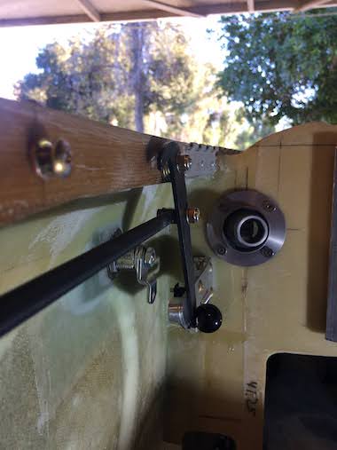 | 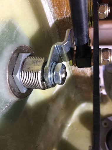 |
| Here is the barrel lock flush with the outside fuselage skin. | 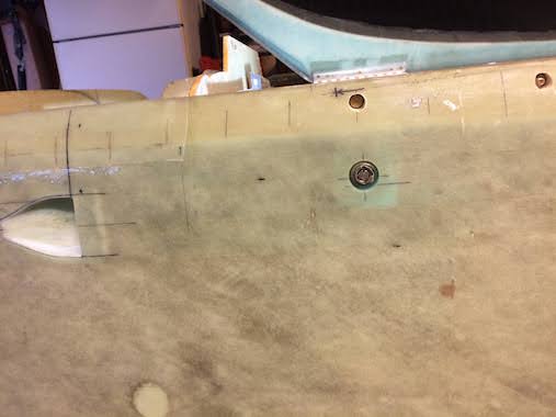 | 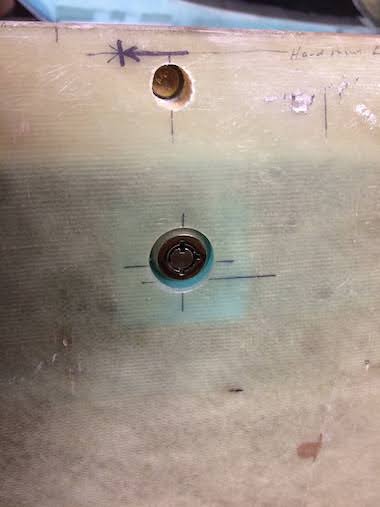 |
| One last thing to do with the shark latch is to add a micro switch that will sound a buzzer or voice alert to warn that the canopy latch is not closed when the throttle position is at a takeoff setting. The only way I could think of to attach it was with flush head rivets but trying to slightly drive/squash the rivet distorted the switch. So I remembered these flat metal clips that are used on car interior panels and are a real pain to take off. They had them at my local hardware store and just the right 1/8" hole size for the flush rivet diameter. Pressed them on and it holds the micro switch solidly. The micro switch could probably be smaller but I had several of them left over from my landing light installation so now I have commonality of parts. | 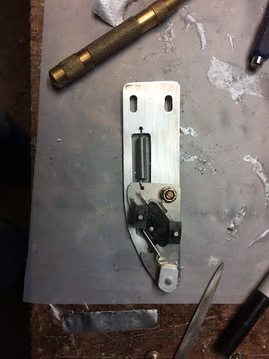 |  |
| Close up of the metal clips pressed on the rivet and holding the micro switch in place. Since the rivets are aluminum the clip really digs into them and they are a real pain to pull off. | 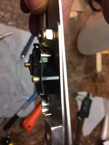 | 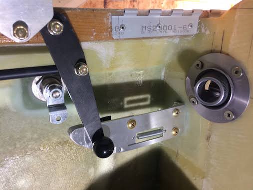 |
| Another close up of the switch and switch specs. I believe I purchased it from Digi-Key. | 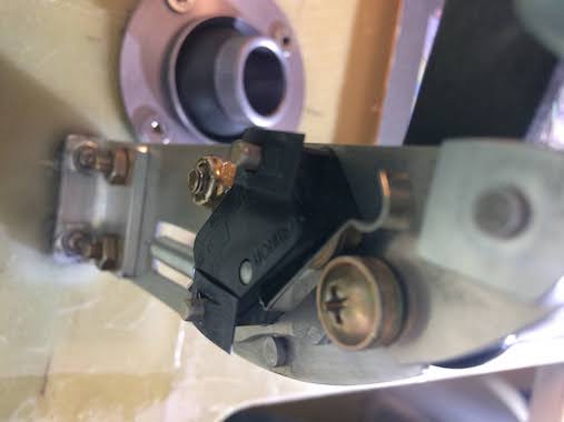 | 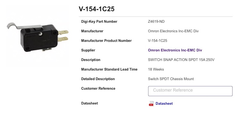 |
Finally to complete the canopy is to glass the pilot's headrest to the canopy bulkhead. I probably didn't need to notch the corners for clearance of the seat belt attach points since the bottom is flush with the bottom of the bulkead which is about a 1/4" above the top of the seat back, but I had done it earlier and will leave it. The attach point of the canopy gas strut just has enough clearance with the edge of the headrest, the plans dimensions worked out perfectly here. The reason the pilot's headrest is attached to the canopy is so that it moves out of the way when the canopy is opened to make it easier for passengers to get into the back seat. | 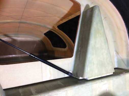 | 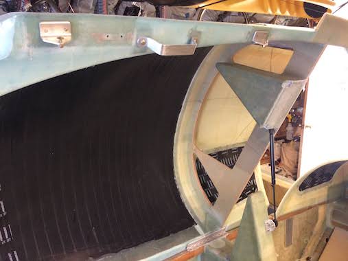 |
March 16, 2021 Well, the canopy is finally done, yeah! Now, to show for all that effort I get to take it off and store it away so I'm able to build the strakes. Extended the loft in one of my sheds so it could sit peacefully. I bondo'd a ply would bulkhead in the aft end to help maintain it's shape. It will get a nice post cure sitting up there in the summer time, hope it doesn't completely melt! Used the block chains to raise the fuselage back up on the rolling cart which will make building the strakes at chest level. | 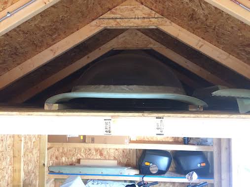 | 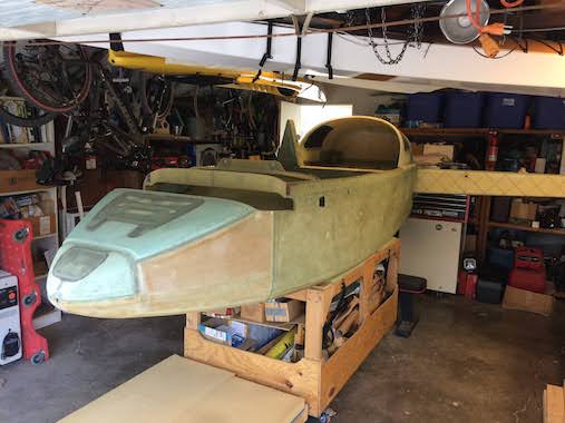 |