This chapter covers the roll and pitch trim control systems. The roll trim controls the lateral, side to side trim, which takes the pressure off the control stick if for example one wing fuel tank is more full than the other, that wing will sag down causing you to roll and turn towards the heavier wing tank unless you compensate with the control stick towards the lighter wing tank. With just a push of the trim lever toward the lighter tank, it will hold the amount you would need to compensate with the control stick. The roll trim system is comprised of a lever, cable, springs and a lever (CZRT-2) attached to the roll torque tube which controls the ailerons. It is a very simple system but a bit of a pain to implement in the airplane due to the amount of tension that must be maintained on the springs, the amount of travel that is needed and the confined space it all has to go in. Also the cables seem to pass through several parts of the airplane that you have already made, the seat supports, the seat bottoms, landing light actuator cover, relocation of landing light return spring among other things. Many people have abandoned the plans system for one that is electrically operated using a servo and an omega shaped spring called the Wright-Hanka Roll Trim, as depicted below by Wayne Hicks in his website. This is installed on the back of the firewall where roll control torque tubes are linked together by what is shown below as the Aileron Pushrod. I was considering this system but thought the plans system would be less complex and lighter and many flyers have said the plans system works fine as you are not having to re-trim roll of the airplane very often.
From Wayne Hicks Website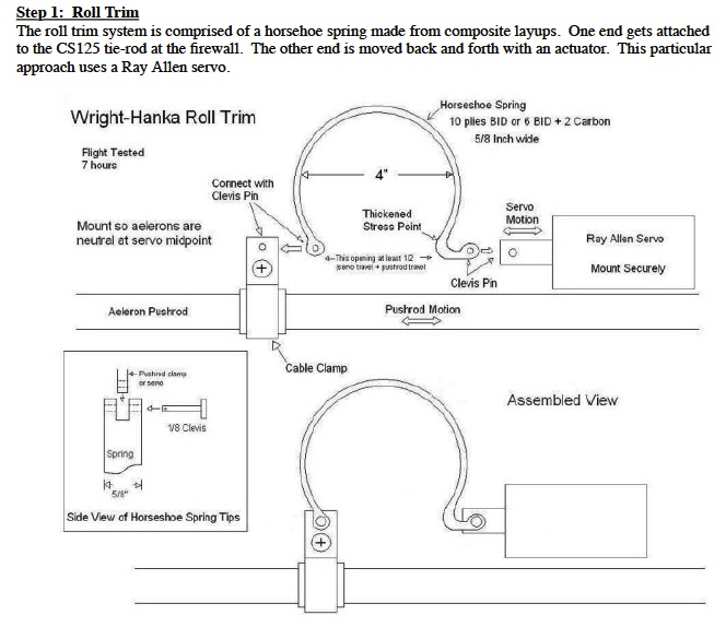
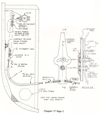
One problem I had was not having the needed 5/8 inch travel as shown in the top sketch from the plans, the sketch in the plans is actually drawn to scale and you can measure off of it. You can measure that the stretched spring is 3 inches as described in the text of the plans and also that the relaxed length of the spring is two inches but the plans did not mention if the spring hooks are included in the the length of the spring which would help in obtaining the needed 5/8 inch travel. I posed the question to the Cozy email group and was told that only the coils of the spring make up the length. Also many people said do not bother with the plans system, but stubborn as I am I will soldier on. It turns out that the thimbles shown as part AN100-3 are much shorter in the plans than the ones I received from Aircraft Spruce. In Bingelis book Sportplane Construction Techniques he says to snip the sharp ends of the thimbles which I had done, but to get the same length as shown in the plans I needed to trim of a 1/4 inch which helped quite a bit. But by the time I figured this out I had whittled away at the guides so now I have about 1 inch of travel, hopefully more is better.
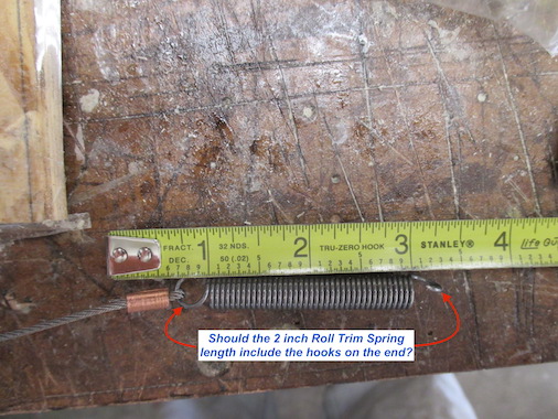
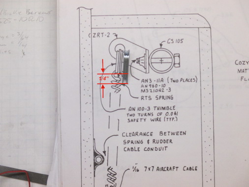
Here is the spring measurement and the 1/4 inch difference between the actual thimble and the one shown in the plans.
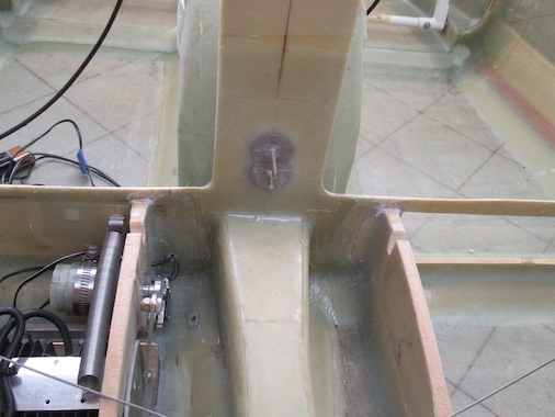
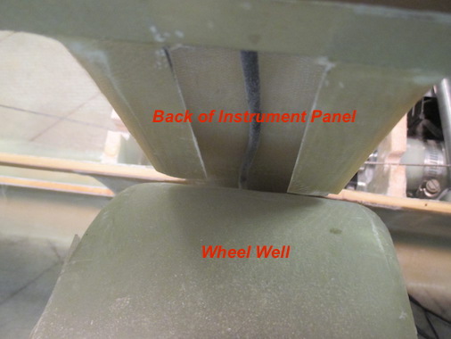
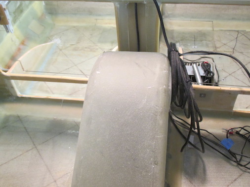
I used Click Bonds with a 1 inch base instead of bolts (shown in top sketch, section A-A) to mount the roll trim lever because there was not enough room between the back of the instrument panel and the nose gear wheel well. I may have made the wheel well a little too big to have adequate clearance between the tire and the wheel well opening.
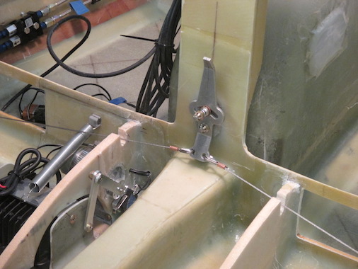
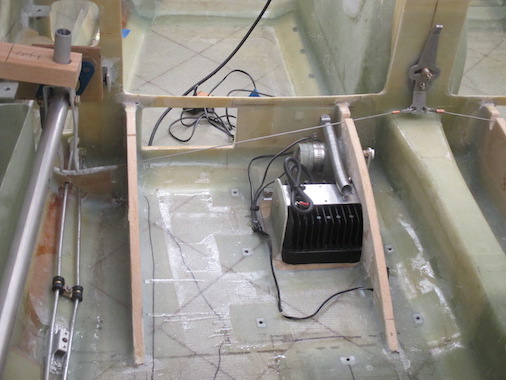
To obtain the proper tension on the roll trim cables the springs need to be stretched to 3 inches with the roll trim lever in the neutral position and the control sticks also in the neutral position. I used a couple of wood blocks to hold the control sticks neutral and tightened the nuts on the roll trim lever to hold that in place. I then threaded the cable through the hole in the lever and pulled the cable with Vice Grips until the spring was stretched 3 inches and marked the cable at the hole in the lever as a reference for swaging the copper nicopress sleeve on the cables with the thimble in place.
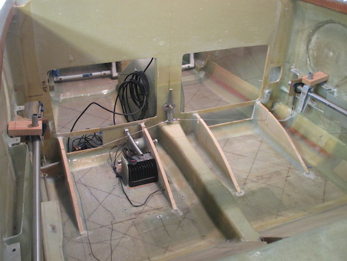

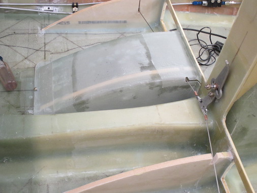
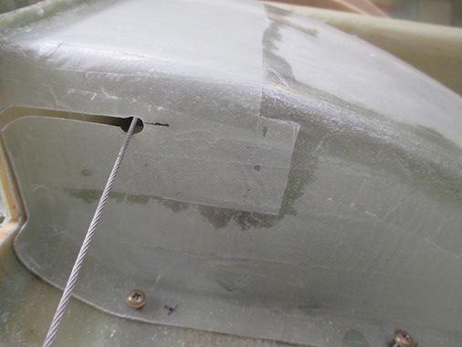
I needed to cut slots in the thigh seat supports for the cables and also needed to move the landing light actuator return spring since the roll trim cable was just touching the top of that. The landing light actuator cover also needed slots cut for the roll trim cable to pass through. I will add a rubber strip to cover the slots in the cover to help block the air when the landing light is deployed.