Sunday Sept. 26, 2010
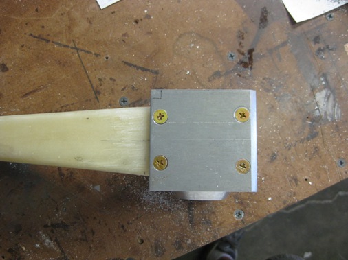
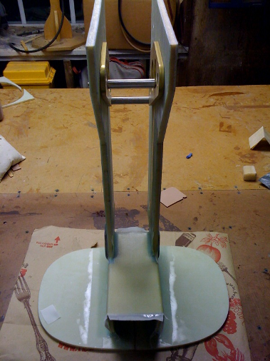
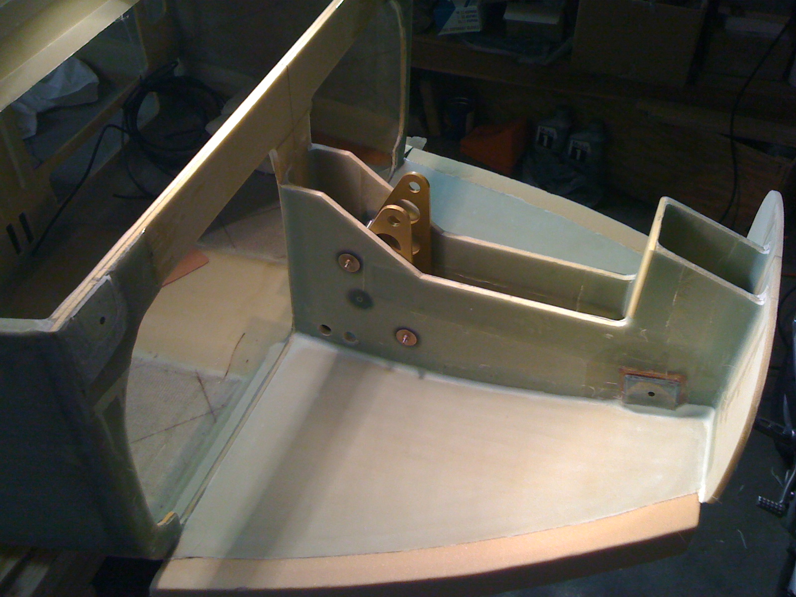
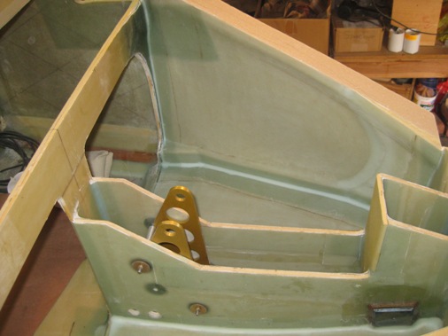
Here you can see the NG-5 plate I fabricated from 1/4" aluminum (2024-T3). This plate helps secure the strut to MKNG-6 pivot and is also supposed to protect the strut in the event of a gear up landing. The holes are already predrilled in the MKNG-6 so I used a drill press to continue the holes through the strut. Then I determined the location of one of the forward holes on the NG-5 plate, drilled and countersunk that and used it to bolt the plate to the strut/pivot assembly and could then match drill the remaining three holes with a hand drill. It's always challenging for us "composite guys" to work with metal specially when accurately locating holes is required. I then alodined the part and floxed it to the strut/pivot assembly using the screws and nuts to clamp it down.
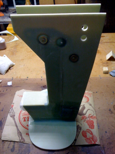
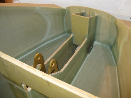
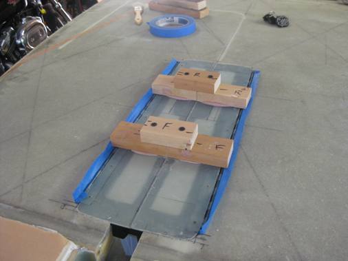
Lynn and I then fabricated bulkheads F-0 and F-5, the plans have you bond them to the NG-30s while they're still wet, but we decided to do it in two steps, well, actually three. F-0 is the most forward bulhead and is located at fuselage station 0, so the nose cone which is forward of this is actually at negative fuselage stations. Bulkhead F-5 is located 5 inches aft of F-0.
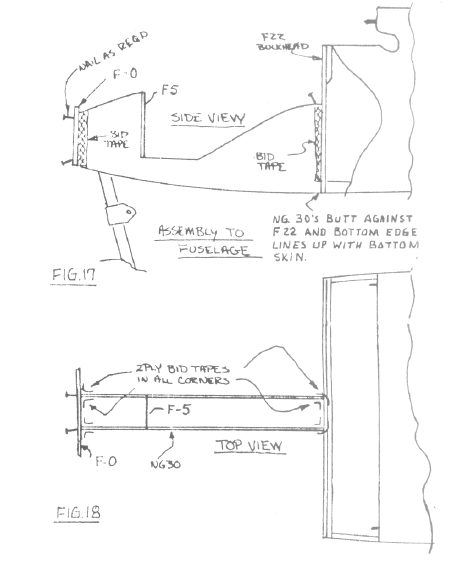
We followed other builders and layed F-0 flat on the table and stood the NG-30 assembly vertically and bonded it with flox and 2 ply BID tapes, making sure everything was as square and vertical as possible. A little tight doing the inside tapes but still manageable. Didn't have time to bond F-5 at this time.
Finally had a chance to bond and glass the F-5 bulkhead to the NG-30's. Because of the design change that raised the sides of the NG-30's by 2 inches and radiused the corner I had to trim the bottom portion of the F-5 sides to fit inbetween the NG-30's.
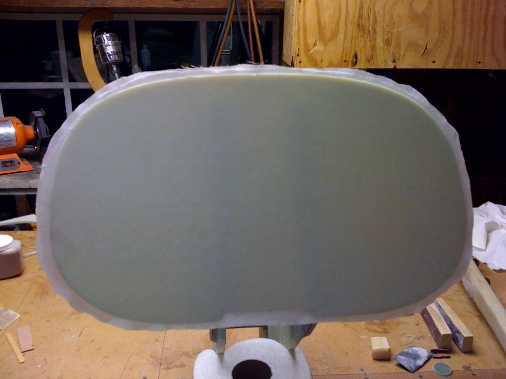
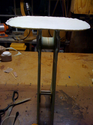
Last thing to do with the nose gear structure before mounting to the fuselage was to lay up 1 ply of BID on the forward face of F-0. I was trying to figure out why the plans only has you put one ply of BID on the forward and aft faces of F-0 when you're floxing all the joints for high strength. The only explanation I can come up with is to make it easier to shape when forming the nose.
Sunday Oct. 3, 2010
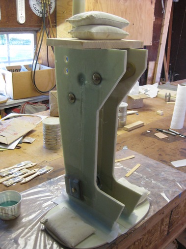
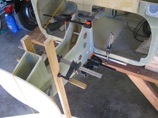
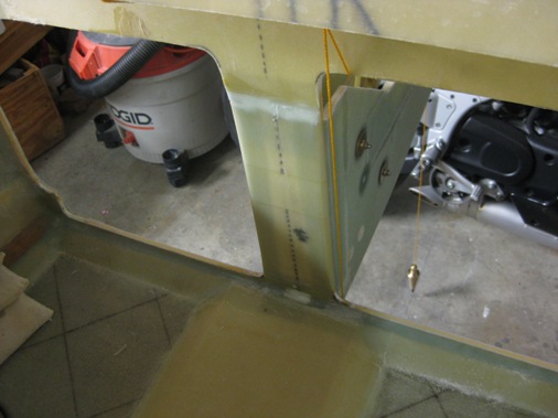
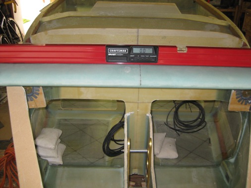
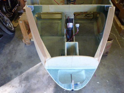
So no more excuses it's time to bond the nose structure to the fuselage, the critical thing of course is to make sure; it's bonded on the fuselage centerline, is vertical and level. To do this I put the main gear back on and re-leveled everything. Then I needed to mark the fuselage centerline on the garage floor and extend it forward beyond F-0. I hung a plumb bob from the firewall and F-22 centerlines and marked the floor. I then 5 minute epoxied nails to the floor in line with the marks to stretch a string. I marked a line along the string and with a straight edge extended it forward beyond F-0.
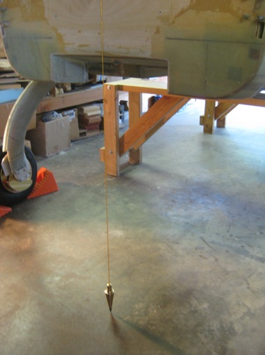
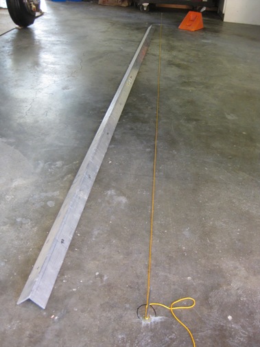
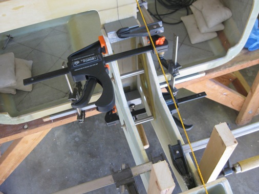
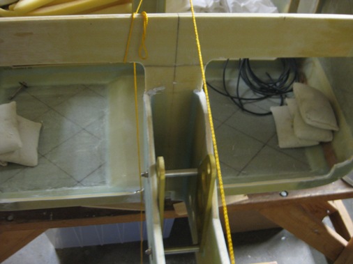
With an arrangement of clamps and blocks of wood covered in "duck tape" I clamped the nose structure to F-22 and hung the plumb bob from the F-0 centerline so that it was lined up with the line marked on the garage floor. I also made sure that the nose strut centerline was lined up with the plumb bob string ensuring that it was vertical. Then I took it all apart and we buttered-up the mating surfaces with flox and clamped it all back together and managed to get everything lined up again. I will add the 2 ply BID tapes after the flox cures.
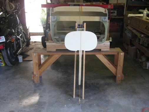
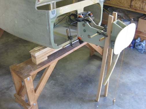
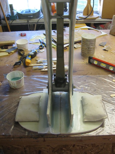
Here's a closer look at the clamping arrangement. The board clamped to the bottom of F-22 allows the nose structure to sit flush with the bottom of the fuselage.
After the flox cured all the corners are taped with two plies of BID.
Tuesday Nov. 16, 2010
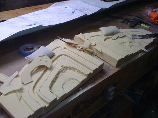
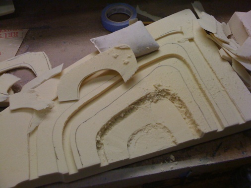
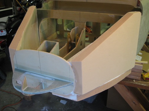
Now it's time to cut the floors out of two inch thick pieces of foam and contour or scallop them to a curvacaeous shape per plans.
I first used a router to get the right depth and then used a knife, smooth sandpapaer and foam to blend and smooth it all out.
Then the foam floor pieces are microed in place.
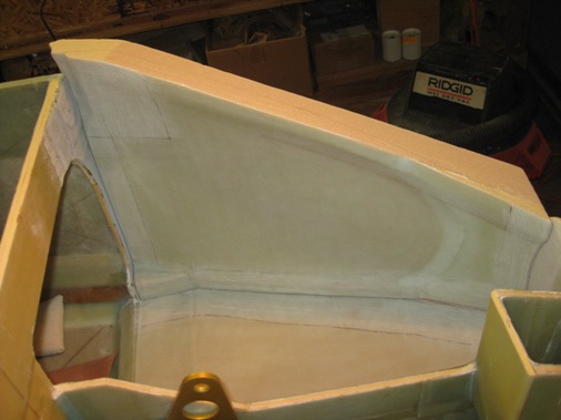
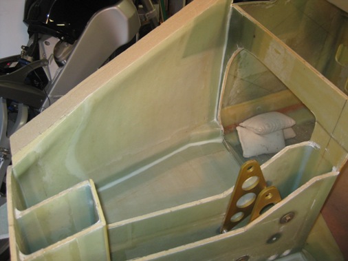
The joggle at the F22 bulkhead is smoothed out with some foam and then the floor is glassed with two plies of bid overlapping onto the NG-30's, F-0's and onto the fuselaged floor by 3.5 inches. another ply of bid 5 inches wide is placed over the joggle for abrasion purposes when the pilot's and copilots feet are slid over the joggle when getting in. A 1.5 inch foam border is left unglassed to make rounding the bottom and side corner easier.
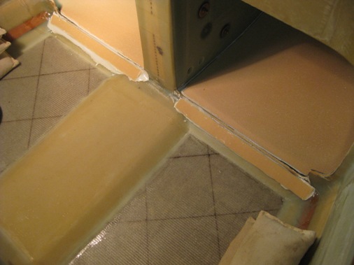
Lastly the nose bulkheads are floxed to F-0, which will also serve as the ballast compartment.
December 2010 & January 2011 Remembering My Parents
During this time both of my parents passed away.
March 13, 2011
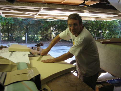
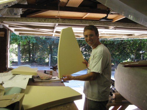
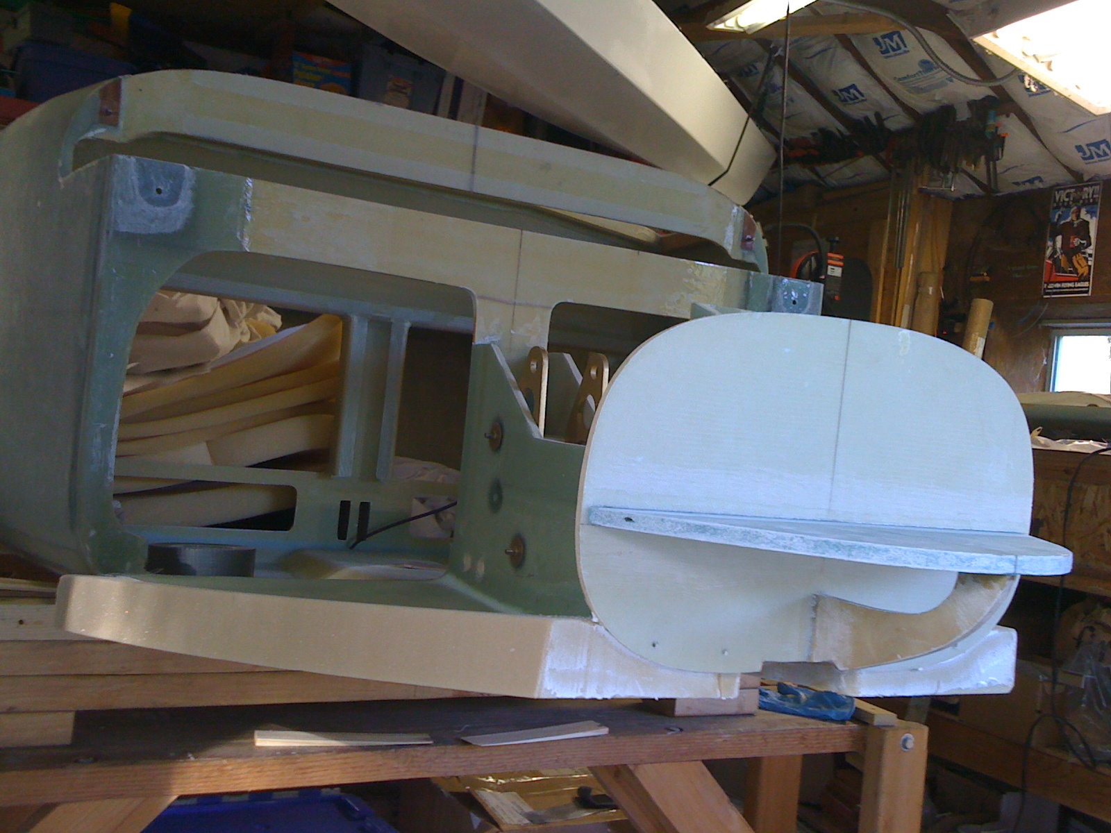
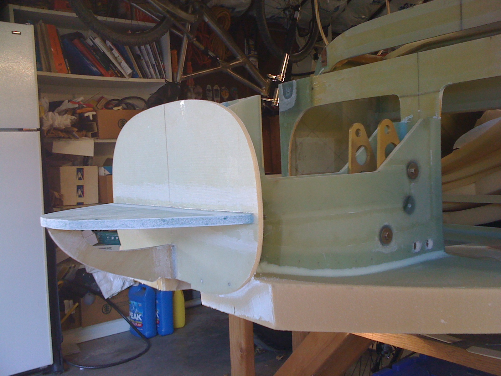
So getting back to work was a bit difficult but the next step was to make the sides for the nose section. This involved carving out the foam similar to what was done for the floor glassing and bonding the side in place with mircro. The plans have you do this all in one step which would seem to me to make a real big mess and reading other builder's experiences it was. So Lynn and I glassed the sides, let them cure and then bonded and taped them in place in the fuselage. Here are some pictures.
Sunday, March 27, 2011
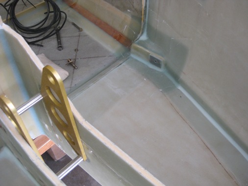
Worked on the rudder pedal attach points. Floxed 18 lb Clark foam in place using the ends of the rudder pedals as a guide to ensure the foam was parallel and perpendicular. After cure drilled a 3/8 inch hole at the pivot point and 5 minute epoxied a nut plate with the rudder pedal bolted (internally) to the nut plate. I made interim CS-13 spacers from 1/4 inch aluminum spacers from the hardware store, needed to drill them out to increase the inner diameter to allow for the AN3 bolt. The CS-13 spacers are made from 4130 steel and have ordered them. Glassed the nutplate with four plies of BID.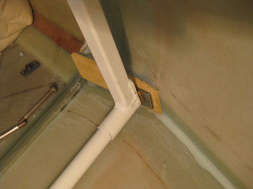
Sunday, April 9, 2011
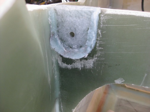
Went back to contouring the sides to allow the canard to fit again, once contoured I realized I didn't provide enough relief for the canard lift tab to slide in place against bulkhead F22. So I cut the four ply layup along the side out and removed foam to allow the canard to fit against F22. Now the mounting pad on F22 for the lift tab was built up with several extra plies of glass so I sanded them down so that the alignment tabs on top would still contact F28. I reglassed the corner with four plies overlapping the mounting pad and after cure made a flox pad to provide a flat surface for the lift tab to bolt to, while ensuring that the canard was still level, at the correct incidence and square with the fuselage. After all this I still had a slight gap between the alignment tabs and F28 so with some advice from Marc Zeitlin I will create a small flox pad there as well to take up the 1/32 inch gap.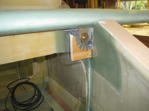
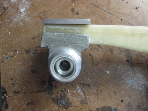
Here you can see the flox pad after cure and then fitting the canard bushing after boring out the 1/4 inch hole to 5/8 with the spot facing tool. The bushing was floxed in place with the canard mounted to ensure all alignment attributes were maintained
Sunday, April 24, 2011
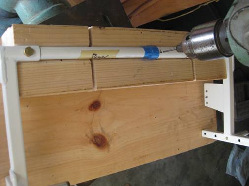
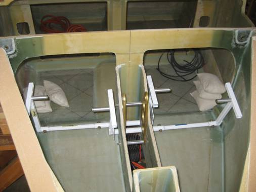
Getting back to the rudder pedals it's time to drill holes and bolt the pieces together. After drilling the first hole I realized that I need to make a jig to hole all the pieces to gether so that everything would be aligned correctly as you see here.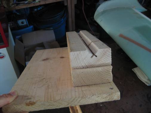
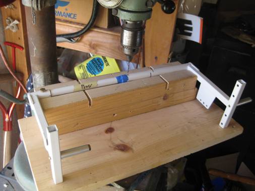
With the jig, drilling the holes on the drill press was easy and everything fit together nicely.
Sunday, May 1, 2011
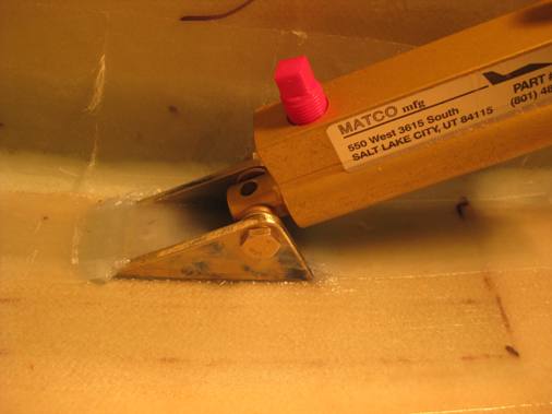
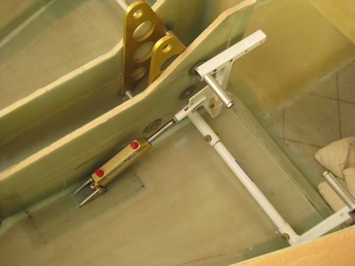
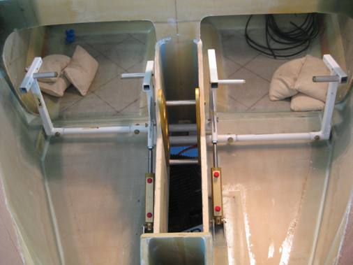
Now it's time to create attach points for the master brake cylinders. I made the brackets from aluminum channel and alodined them. The blue smudging on the brackets I believe is from the scrub pads used to clean the aluminum with the surface prep solution. I needed to shorten the rudder pedals a bit to get full travel of the master brake cylinder without the pedals hitting the side wall. I built up the floor with an extra three plies of BID locally to the bracket attach location. The bracket was floxed and pop riveted to the floor with more flox and three plies of BID over the top.
Monday, May30, 2011
Went to the Canards West flyin this weekend at Columbia airport in Nothern CA. It was inspiring to see all the Cozy's and LongEZ's and a bit overwhelming to realize how much more there is to do and the attention to detail involved to actually get an airplane flying. It's amazing how friendly the community of canard builders and flyers are willing to talk to you and show you how they did certain things on their airplane. Even Dick Rutan and Mike & Sally Melville were there just hanging out talking about airplanes. From talking to other builders I'm finding that we are all in the same situation trying to find time to build and overwhelmed by the amount of work. The reality of it is that once all the structure is complete you're half way done. I would say that I have a quarter of the structure done so that gives you an idea of what's left.
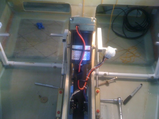
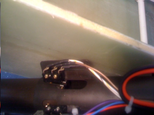
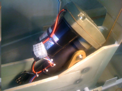
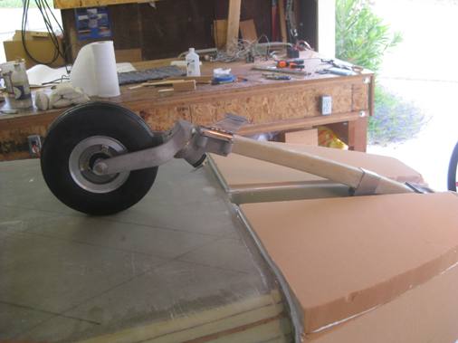
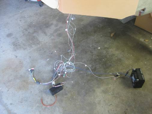
So I've been struggling a bit with the nose gear actuator, specifically the outrageous bundle of wires that come with it. The wires are intentionally left long to accommodate vairous routing configurations, so many of the wires are left unterminated, meaning you have to crimp and solder pins to the ends of the wire and insert them in the correct location and connector. All of the wires are labeled except for one in my case. A wire diagram is provided but the wire colors don't necessarily match the colors in the diagram which is made known in the instructions but was a bit frustrating for me. So I decided that I would just start out and crimp and solder the pins to the ends of the wires, and after completing most of that task I realized that I had too much wire inserted into the pin which was the female end and therefore would not allow the male end to plug into it. Of course none of the local electronics stores had the right pin so I emailed Jack for the pin part number which he promptly replied, Molex 02-08-1002-C. Mouser 538-02-08-1002. So I ordered them from DigiKey which took about a week to get. So I finished terminating the wires correctly and spent the good part of a day trying to figure out the wiring, I probably should not have thought about it so much and just did it. When all was said and done I had one blue wire which I didn't know what to do with and determined that it must be the ground wire. So, with figures crossed I hooked the bundle up to the actuator and the power and ground wires to an old motorcycle battery. I also wired in a safety switch so I could shut off the power quickly. Power On and the gear select switch set to down and the actuator started to extend, Yahoo! The led lights on the panel also illuminated correctly. I needed to have the actuator in the full extended position to determine the final location of the nose wheel and finally drill the holes in the actuator brackets to finish that installation.
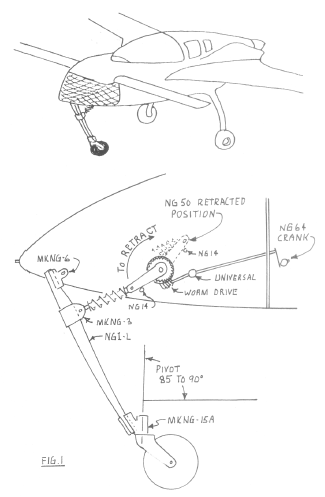
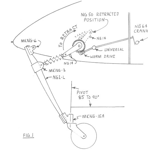
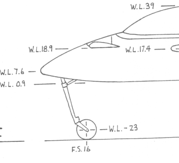
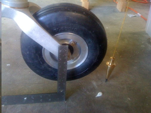
Determining the correct position of the nose wheel can be done a number of different ways, the plans just have you make sure that the piviot is at 85 to 90 degrees. The airplane graphic on the back of the plans showing the fuselage stations shows the center of the nose wheel at fuselage station FS16 which is the reference that Bernie Siu used on the advice of visiting Wayne Hicks which seems to make a lot of sense. Jack Wilhelmson's instructions say that the longerons should have a positive up slope of 1.5 to 2.0 degrees to ensure the canard is at a good angle of attack on the take-off ground roll. To achieve that required positioning the actuator brackets quite a bit forward and I would need to create new hard points in the NG-30's. Also since Jack's instructions are meant for retrofiting an existing airplane I don't know what affect the weight of the engine in back would have on the angle of the longerons and if that would be equally offset by the weight of the passengers in front. So I decided to follow the references in the plans. I determined F.S.16 by dropping a plumb bob from the front of F-22 and measured 6 inches forward of that and with the nose wheel at that location the pivot seemed to be within the range of 85 to 90 degrees.
The only problem was that the bracket was still angled too far forward to pick up the holes in the NG-30 hard points. I was still thinking that I'd have to make new hard points but first I'd try adjusting the down limit switch on the actuator to see if I could get more travel. I adjusted the limit switch to just about the end of the slot and powered it up and extended the actuator further. With that adjustment the bracket position was far enough back to caputre the holes in the NG-30 hard points. I'll hold off drilling the holes in the actuator brackets until I see if the actuator will retract the nose gear completely within the bottom of the fusealge. So now I need to flip the fuselage over and cut a hole in the bottom for nose wheel to retract into. I also plan to incorporate gear doors instead of leaving the hole open to the free stream air flow.
Sunday, June 5, 2011
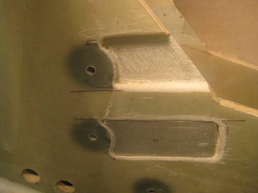
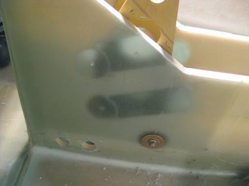
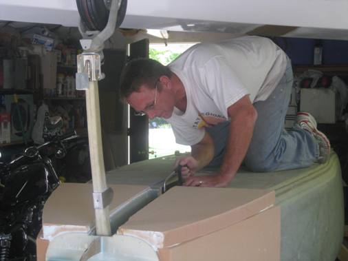
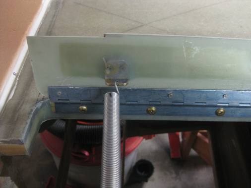
After being elated that I wouldn't have to make additional hard points I decided to set the fuselage down on the nose wheel to see whether the fuselage longerons would be level. With the weight of the fuselage on the nose wheel and slop in the pivot points the centerline of the wheel moved aft about an inch or two. Two get the nose wheel far enough forward to the FS16 point the brackets needed to be moved forward beyond the existing hard points in the NG30's. So I decided to bite the bullet and extend the hard points, this way I could move the limit swtich on the actuator back to the middle which would give me more adjustability later when the plane is loaded with an engine in the back and instruments and avionics in the front as well as passengers.So I layed up 20 plies of BID to create the hard points and let that cure overnight. Then I routed out slots forward of the original hard points angled slightly upward to account for the arc that the bracket makes when positioning it foward. I floxed the hardpoints in and covered everything with 4 plies of BID. With the back lighting it's easy to see where the bracket and hard points overlap as an area for drilling a mounting hole.
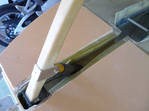
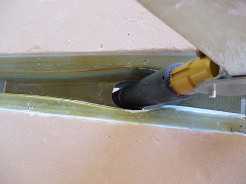
Sunday, June 12, 2011
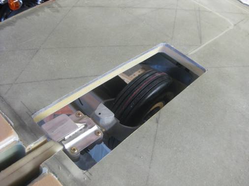
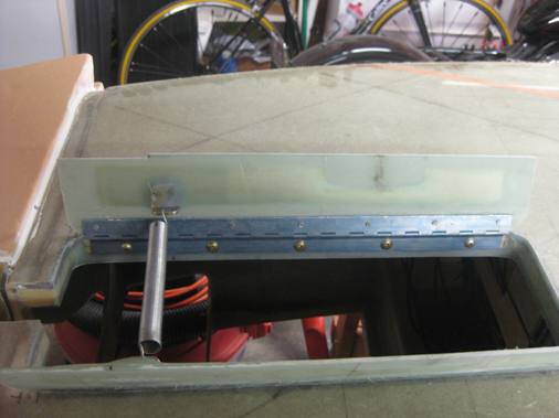
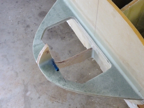
Now it's time to get serious about getting the nose gear to retract into the fuselage which means cutting a hole in the bottom so it has some place to go. I decided that I would depart from the plans and incorporate nose gear doors per Wayne Hicks' design. So instead of an oval hole I would have a trapezoidal cut out that is slightly wider in the front and narrower in the back. The reason for this is that the airflow will help keep the doors open in flight. I cut the straight lines with the Fein sander and the rounded corners with a jigsaw. I had to recut the straight lines with the jigsaw to cut through the entire thickness of the floor. As you can see in the picture I used a small hacksaw to open up the slot in F22 to make clearance for the nose gear strut. After some adjusting of the actuator limit switches I was able to get the nose wheel to fully retract within the fuselage with a half inch of clearance between the top of the tire and fuselage bottom, may not need this much. Jack's instructions say to make sure there is a full turn of the jackscrew left after the retract limit switch stops to provide some final adjustment later. By setting the retract limit switch as prescribed, essentially sets the position of the actuator brackets and as it turns out I may be able to use the original upper NG30 holes and will probably have to drill new middles holes. This is good because the upper holes need to be perfectly aligned through the NG30's to permit threading a spacer in-between the brackets.
Sunday, June 19, 2011
I made the nose gear doors from 8 plies of BID with 1/4"foam sandwiched in the middle to add rigidity. The foam at the edge of the hole is recessed to accommodate 1/4" plywood strips with 1/4" thick aluminum (5/8" square) slugs floxed on the back to provide threaded holes for mounting the door hinges, similar to what was done for the speed brake back in Chapter-9. The plywood strips also have a 45 degree bevel along the long sides to provide a flox corner on the top and bottom of the hole.
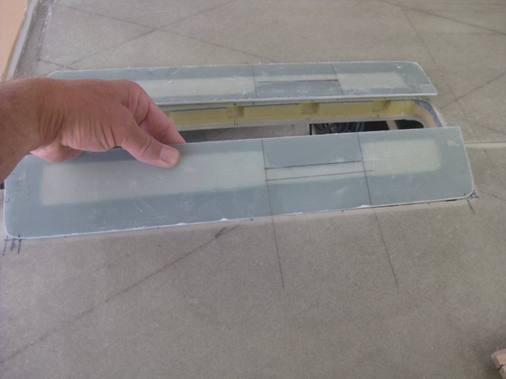
The 8 plies of BID resulted in the door being an 1/8" thick along the edge and with the embedded foam is very stiff, might be overkill. May need to modify it a bit to provide a flat spot for a small bracket for attaching the spring. I'll also need to open up the forward section to make room for the parking support foot to protrude through. Rick Irwin's Site has a video of his nose gear doors closing around the parking foot.
Sunday, July 10, 2011
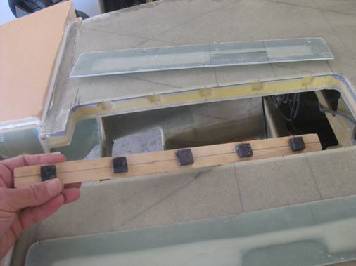
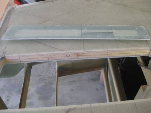
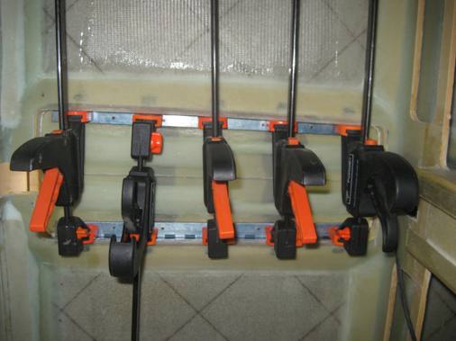
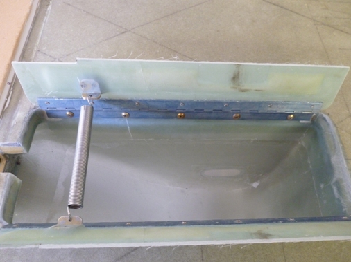
Now the challenge is of course to attach the doors to the hinges, the hinges to the opening and have the bolt holes line up and the doors flush with the bottom of the fuselage. I matched drilled holes in one half of each hinge with the plywood strips with the aluminum slogs and threaded the slugs for screws. Then I floxed the doors to the hinges and after cure riveted them with flush head rivets. Then I assembled the hinges so the doors are hinged to the plywood strips. I bondoed the doors together with strips of wood and then cut the strip of wood at the center line and screwed another block of wood on top, I couldn't get the assembly in the hole otherwise. Then I floxed the wood strips into recess in the hole cutout and held them in place with spreader clamps. I did remember to fill the back of the screw holes with wax. After that cured I unscrewed the door/hinge assembly from the plywood strips which are now permanently floxed in place, filled the holes completely with wax and floxed the corners and laid up 2 plies of BID around the opening including over the plywood strips.
I opened up the screw holes and reassembled the doors to the opening and trimmed the doors so that they would open and close smoothly and cut a slot for the parking standoff on the strut.
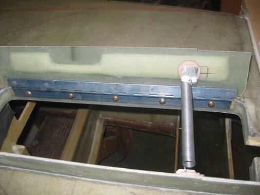
I made some aluminum brackets from the aluminum channel I used for the master brake cylinder attachments and bondoed them in place where I thought they would contact the MKNG-15A (swivel) in the correct spot (per other builders websites). I verified that the strut contacting the spring closed the doors by hand and then by the actuator. Pretty amazed that the doors close fast enough to prevent getting caught on the parking standoff, but they do, I'll include a video when it's finally assembled. Needed to order some flush head pop rivets to rivet the brackets to the door. The spring was from the local hardware store a #194 which was 7 inches long, 1/2 inch in diameter and 0.062 gauge. I needed to cut the spring shorter to accommodate the opening which I did with some small bolt cutters and then bending one coil to create a hook.
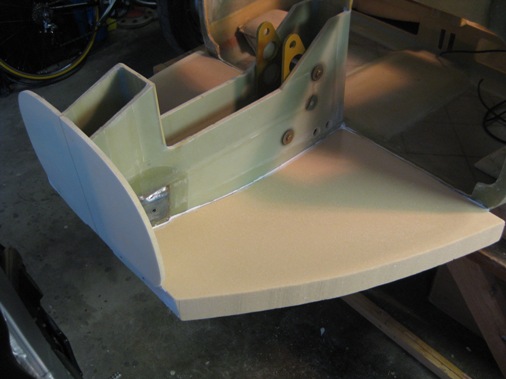
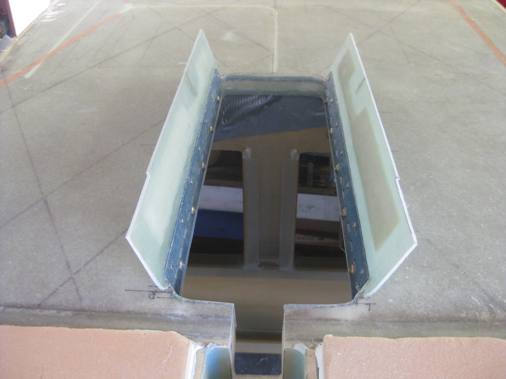
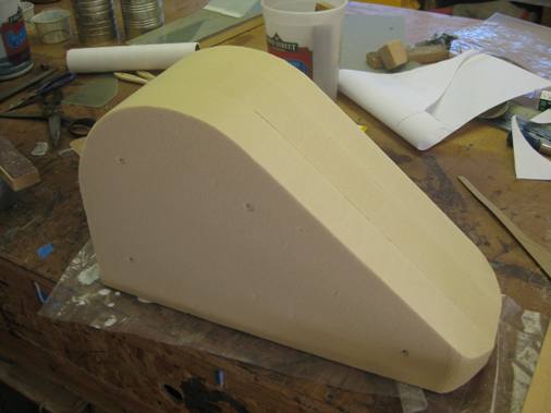
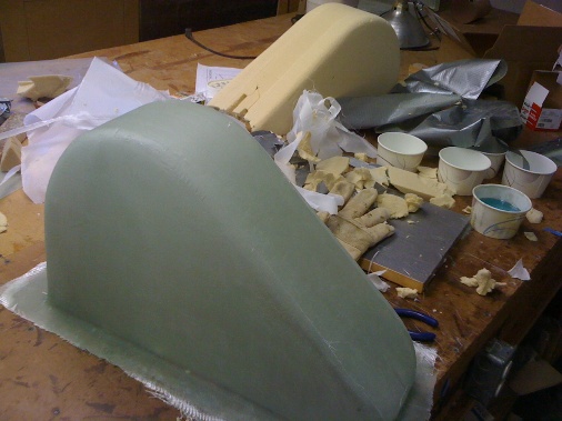
While waiting for the pop rivets I decided to make the wheel well that encloses the nose wheel within the fuselage. Based on the plans drawings and the nose wheel opening I made some templates to create a mold. For the mold I microed three 2 inch thick pieces of urethane foam together and shaped it per the templates to a somewhat pleasing shape and covered it with duck tape. The plans have you glass it in place in the fuselage I believe so that the bottom will conform better to the fuselage floor but that would be a bit difficult considering the close quarters, so Lynn and I glassed the mold with three plies of BID on the work bench which I will trim to fit the fuselage floor.
Sunday, July 17, 2011
Finished the nose gear doors by pop riveting the brackets on with flush countersunk rivets and flox and 2 plies of BID.
Here are some videos of the nose gear operating with gear door actuation.
<> <>Sunday, Sept 10, 2011
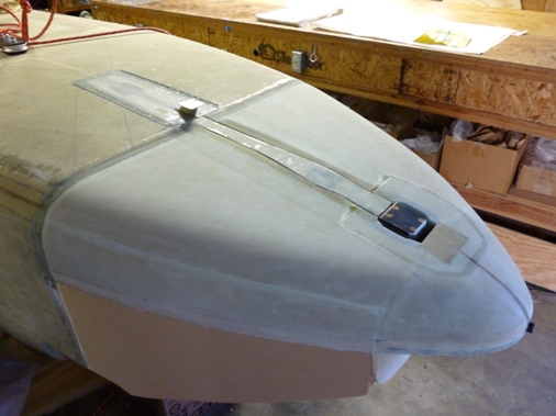
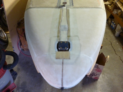
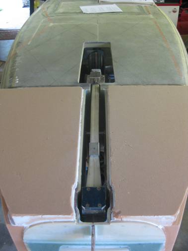
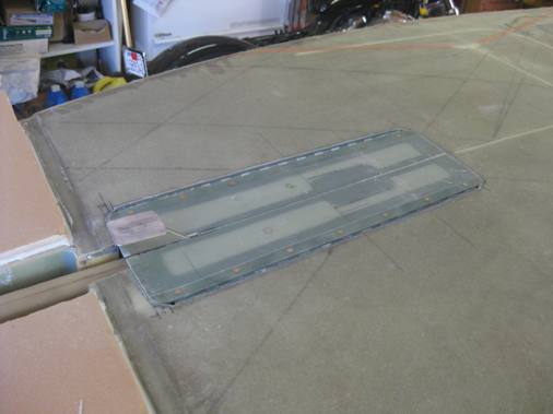
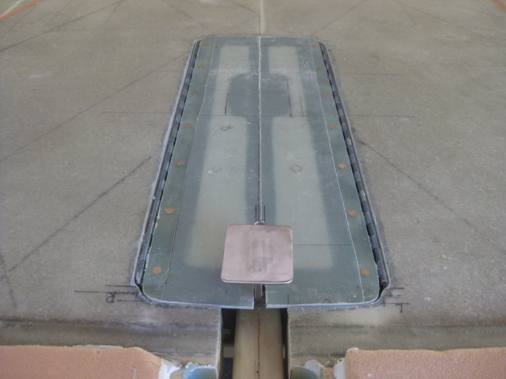
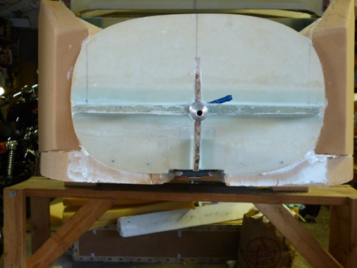
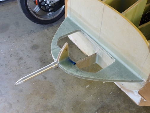
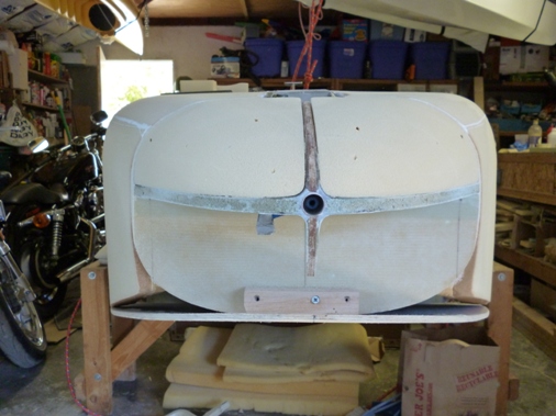
The wheel well is now installed, the ovals are plexi glass windows to see when the nose gear is retracted (they're covered with tape to avoid scratches).
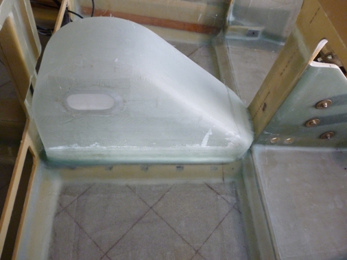
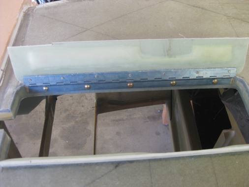
I also floxed in the prefabricated strut cover.
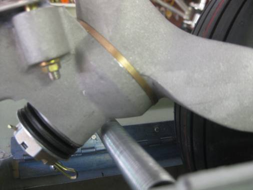
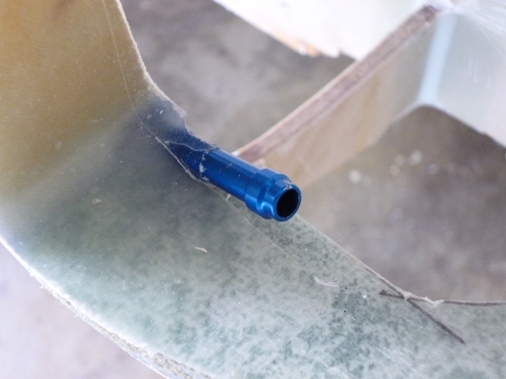
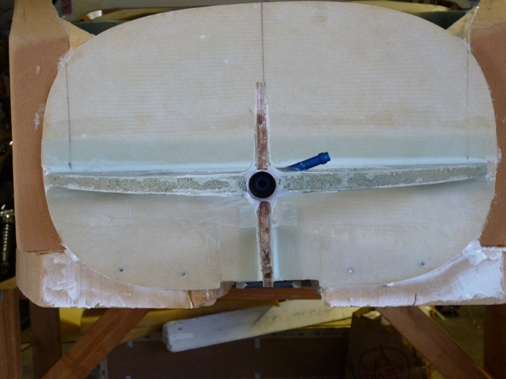
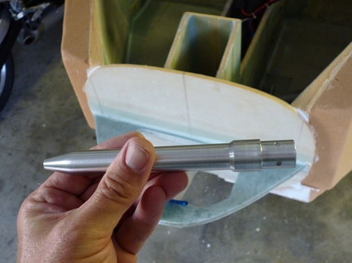
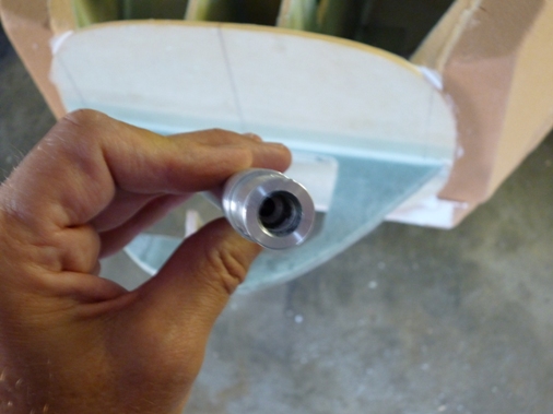
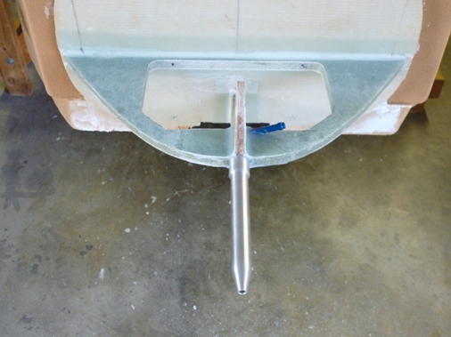
The pitot tube is installed which I made removeable using an AN842-4D elbow which has a hose nipple on one end and a 1/8 inch male pipe thread on the other. The pitot tube p/n 15170 (Aircraft Spruce) also has 1/8 inch pipe threads so it threads on nicely. I may have to cut the pitot tube shorter so that it won't hit the ground when the airplane is parked nose down. I floxed the AN842-4D fitting inside a 3/4" (.049 wall) aluminum tube and then floxed that in the center of the cross section of NG-31 and NG-32. The pitot tube fits nicely inside the aluminum tube and threads on to the fitting, this idea came from Wayne Hicks'website.
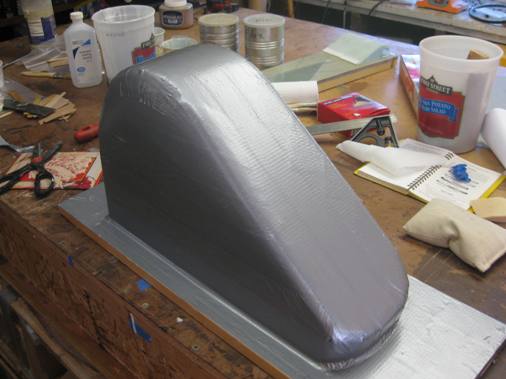
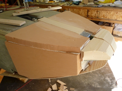
Took a couple of tries to bond the foam blocks for the nose section without getting mirco at the curve lines to make shaping easier.
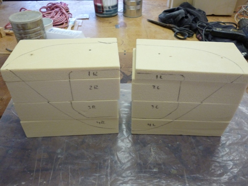
Sunday, Sept 25, 2011
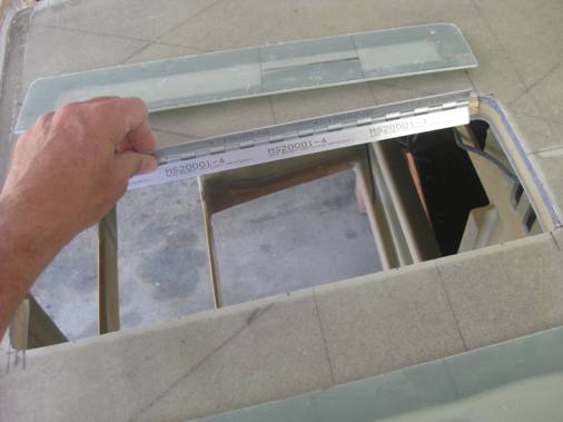
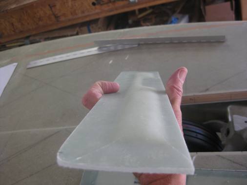
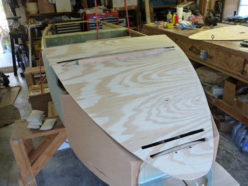
I've been a bit intimidated to shape the nose section so I decided to make some plywood templates as a guide for sanding the foam. Of course I plagiarized this idea from Wayne Hicks by measuring the fuselage width starting 20 inches aft of bulkhead F20 and then using the NG31 template for the nose and using a flexible piece of wood (batten) to merge the curves of the fuselage section and the nose section.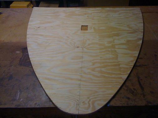
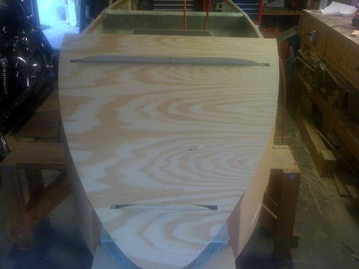
It looks like I'll need to add some extra foam to achieve the template curve. This presents a problem because a micro joint to attach the foam will make sanding a smooth curve impossible. I found an article on the EZ Squadron website on shaping the nose of a Varize; Nose Art which provides good information on using pour foam from Hastings Plastics to attach foam blocks together which will allow smooth shaping through foam joints. So I will try that, fortunately Hastings is local to me in Santa Monica, CA so I can pick it up on my way home from work.
Sunday, Oct 2, 2011
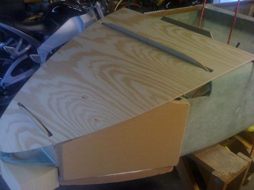
It turned out that I didn't need to add extra foam to the sides, I just needed to reposition the template in the correct spot. I did experiment with the Hastings pour foam and liked it a lot. I bought the 2lb density polyurethane pint size cans and it bonded two pieces of foam with a very thin skim coat and looked and sanded like the regular foam. It would have been perfect for bonding the nose blocks together.
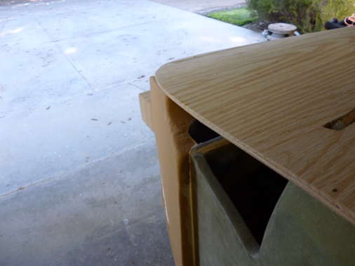
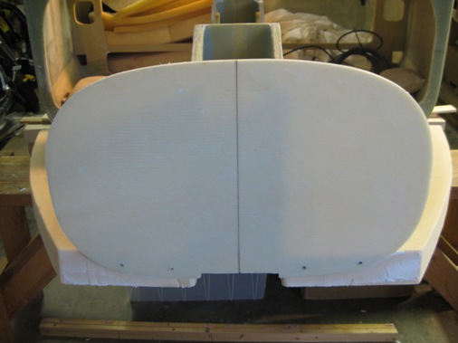
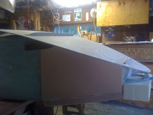
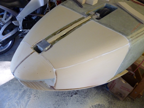
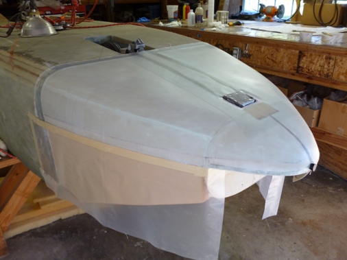
With the templates positioned correctly we started sanding and followed the plans by doing the bottom first.
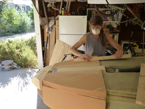
Then we did the sides following the contour of the templaes.
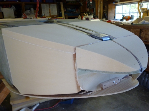
And finally rounding the corners. Some of the micro joints we had to file down.
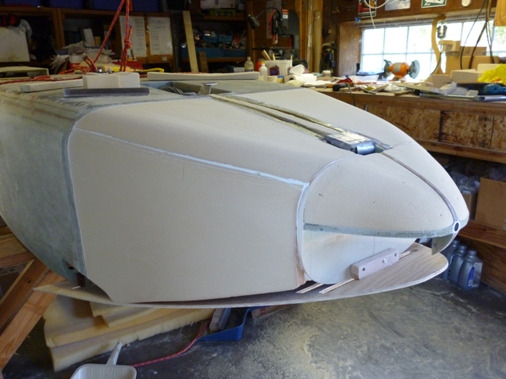
Overall we're very pleased with the outcome especially since you only have one chance at it. I'll follow what a number of other builders have done and save shaping the top of the nose section when building the canopy so that there's a smooth contour from the base of the plexiglass windscreen, over the canard to the nose. I would have liked to finish the nose section now so the foam would be protected with a fiberglass skin, but better to be patient.
Sunday, Oct 9, 2011
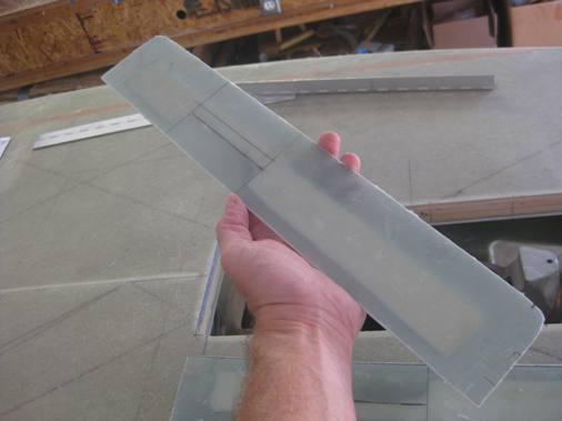
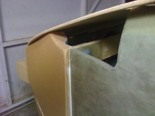
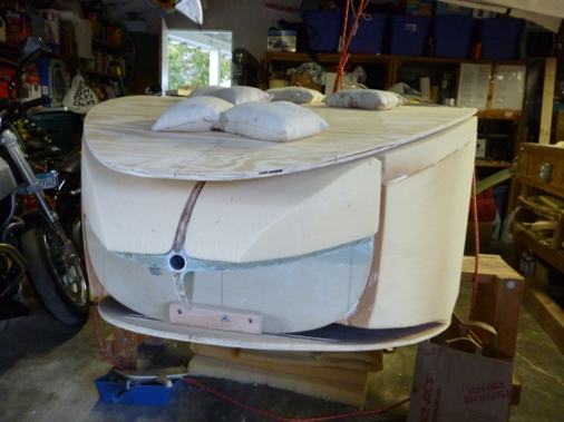
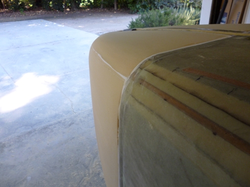
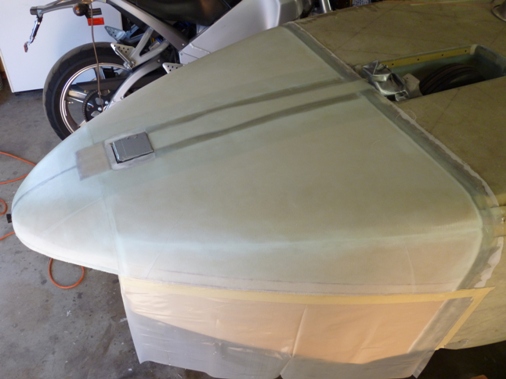
After a few hours of grinding all the joints as smooth as possible we covered the bottom of the nose section with 2 plies of BID and a third 8 inch wide ply down the middle. The second ply is cut an inch shorter that the first (reason for the lines) to avoid a bump when overlapping the glass from the upper section.
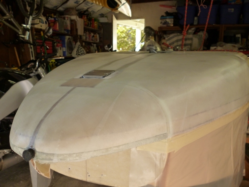
The nose gear strut will be cutout with a box knife after a few hours of cure when the glass hardens to the chewing gum stage.
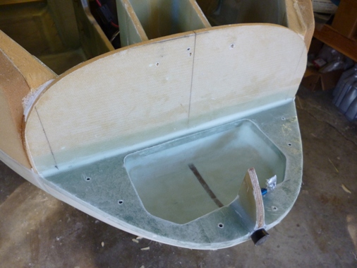
Flipped the fuselage over, scalloped out the foam and glassed the lower ballast compartment area.
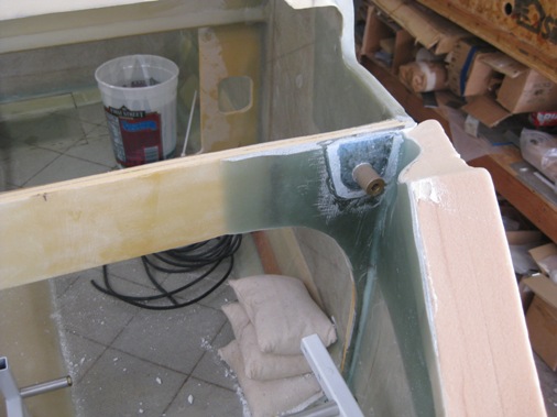
Sunday, Oct 30, 2011
Finished up some minor details on the strut cover and made a flox corner to fill the gap in the area around the strut pivot. We'll call it a wrap on Chapter 13 for now saving the top of the nose section for Chapter 18 when the canopy and turtle deck are constructed. So time to move on to Chapter 14 and build the center section wing spar.